Overview
Description
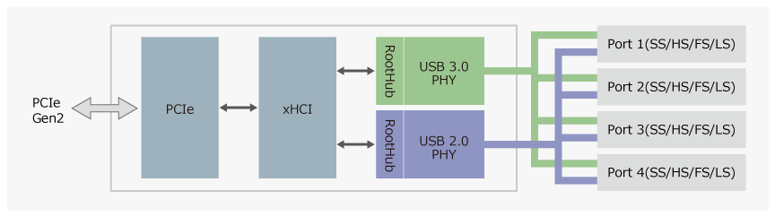
The µPD720201 is a USB host controller LSI compatible with the USB 3.0 and xHCI (eXtensible Host Controller Interface) 1.0 specifications. The system bus is compatible with the PCIe Gen2 specification. The controller provides four USB ports with LS (Low-Speed) / FS (Full-Speed) / HS (High-Speed) / SS (SuperSpeed) support.
The µPD720201 comes in a 68-pin QFN package and has the following improvements over previous products.
- Reduced power consumption in low-power mode to 4.5mW, a reduction of 90% compared with Renesas Electronics' existing products
- Improvements to the data transfer processing circuit provide an increase in the effective data write speed of more than 40% from existing products
- Firmware download function eliminates the need for external serial flash ROM
Features
- System I/F: PCIe Gen2 x 1 Lane
- USB ports: 4 ports (SS/HS/FS/LS)
- Comply spec to: PCIe 2.0 Base Spec
- USB 3.0 rev1.0 (USB-IF certified: Test ID = 380000050)
- Intel xHCI rev 1.0
- VDD: 1.05V, 3.3V
- Clock: 24MHz Xtal clock input
- Package: 68-pin QFN (8mm x 8mm, 0.4mm ball pitch)
- Ta: 0~85 °C (μPD720201K8-701-BAC-A)
Ta:-40~85 °C (μPD720201K8-711-BAC-A)
Comparison
Applications
Documentation
Featured Documentation
Log in required to subscribe
|
|
|
|
|---|---|---|
| Type | Title | Date |
| Datasheet | PDF 1.37 MB 日本語 , 简体中文 | |
| Technical Update | PDF 209 KB | |
| Manual - Hardware | PDF 1.85 MB 日本語 , 简体中文 | |
| Application Note | PDF 219 KB | |
| Guide | PDF 1.03 MB | |
5 items
|
||
Design & Development
Software & Tools
Boards & Kits

Reference Designs
uPD720201 PCIe Add-In Card Reference Design Board
The μPD720201 is a Renesas' third-generation Universal Serial Bus 3.0 host controller that complies with Universal Serial Bus 3.0 Specification, and Intel’s eXtensible Host Controller Interface (xHCI). This device reduces power consumption and offers a small package footprint making it ideal for...
Models
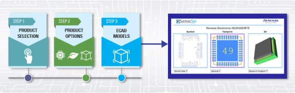
ECAD Models
Schematic symbols, PCB footprints, and 3D CAD models from SamacSys can be found by clicking on the CAD Model links in the Product Options table. If a symbol or model isn't available, it can be requested directly from SamacSys.
Product Options
Applied Filters:
Support

Support Communities
Get quick technical support online from Renesas Engineering Community technical staff.


Support Communities
-
Can you provide UPD720201K8-711-BAC-A IBIS file?
We want to do simulation, can you provide UPD720201K8-711-BAC-A IBIS file?
Aug 8, 2024 -
RTKA720201DE0000BU (uPD720201) not Working with Windows 10 Computer
Hello, I have been having trouble getting the RTKA720201DE0000BU demo board to work in Windows 10. The device is recognized by the motherboard and shows up in the BIOS as a USB device, but when viewing it in the device manager, the following error appears in the device status: This ...
Oct 16, 2024 -
UPD720201 compatibility issue.
We have a compatibility issue regarding to USB controller IC UPD720201K8. We did hot-plug test and it will stop responding / detecting. Could you provide some advice. OS: Ubuntu 22.04.5 Reproduce step: 1. Powe off/on the SUT2. Boot into OS3. Plugin USB hub(ORICO model ...
Jan 7, 2025
FAQs
-
What is common mode rejection (CMR) of an operational amplifier?
CMR indicates the ratio of the input voltage to the varied input offset voltage when the input offset voltage has changed due to a change in the input voltage. CMR=ΔVI/ΔVIO Normally the DC variation is the target. If the CMR value is large, it indicates that, when ...
Dec 1, 2011 -
What is the maximum output voltage (Vom) of an operational amplifier?
This expresses the limit value at which the output of the operational amplifier is saturated when the prescribed power supply voltage is applied. There are two values: one for the positive power supply side and one for the negative power supply side. In addition, either a load resistance value (2 ...
Dec 1, 2011 -
What is offset voltage?
In an operational amplifier, the output voltage should theoretically be 0 V when the voltage differential between the input pins is 0 V. However, in reality, VBE of the positive and negative input transistors in the input stage's differential amplifier circuits differs. As a result, the voltage differential between ...
Mar 1, 2006