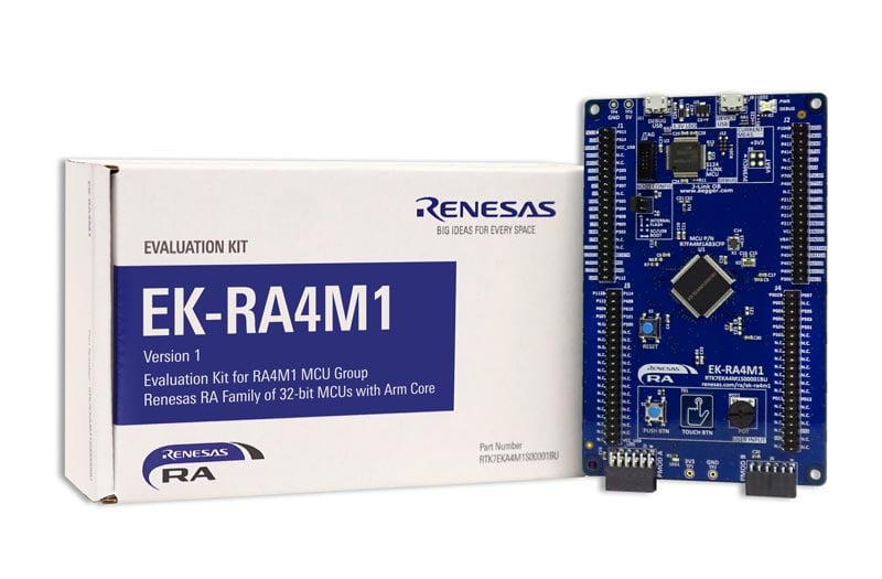
Overview
Description
The EK-RA4M1 evaluation kit enables users to effortlessly evaluate the features of the RA4M1 MCU Group and develop embedded systems applications using Renesas' Flexible Software Package (FSP) and various IDEs.
Getting Started
Running the Quick Start Example Project
- The EK-RA4M1 board comes pre-programmed with a Quick Start example project (Provided with the example projects bundle).
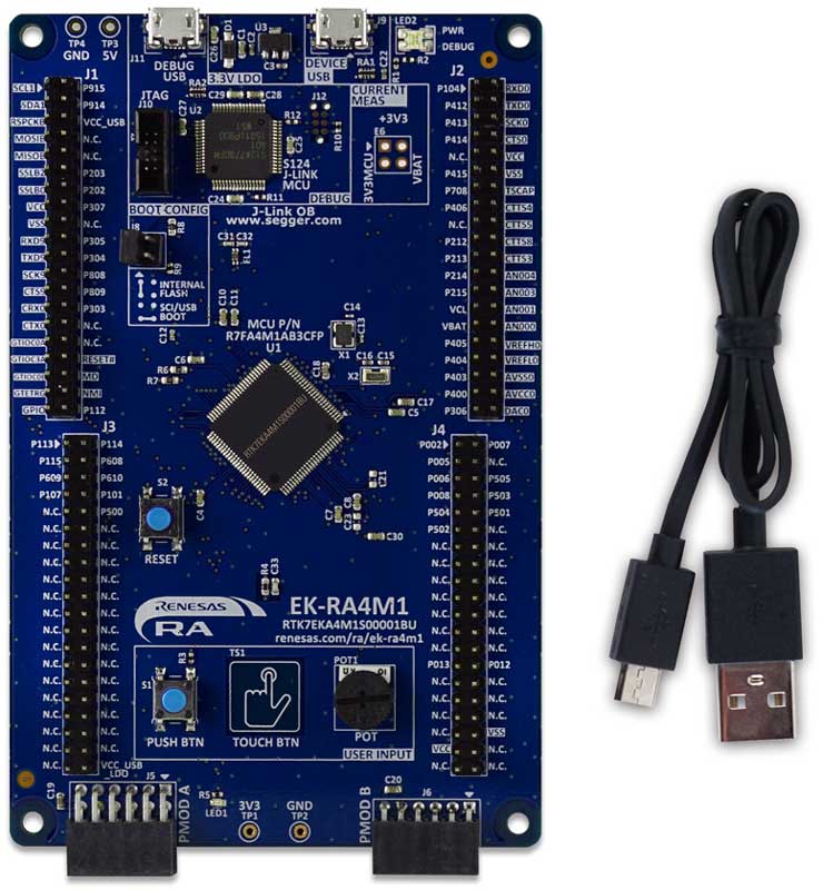
- Power up the EK-RA4M1 board through the USB debug port (J11) using the micro USB device cable connected to a 5V power source. The green power LED will light up.
- The Quick Start example project will begin to execute blinking the red user LED.
- Refer to the EK-RA4M1 – Quick Start Guide (PDF) to explore additional functionality of the Quick Start example project.
Developing Embedded Applications
- Modifying the Quick Start example project – Refer to the EK-RA4M1 Quick Start Guide for instructions on importing, modifying, and building the Quick Start example project.
- Start with one of the many other example projects (Provided in the example projects bundle) – Choose from many example projects to learn about different peripherals of the RA4M1 MCU group. These example projects can serve as an excellent starting points for you to develop your custom applications.
Building Custom Hardware
- Start by building a functional prototype - Utilize the EK-RA4M1 board with your choice of ecosystem add-ons.
- Build custom hardware – Develop custom hardware by referring to the design and manufacturing information provided in the EK-RA4M1v1 - Design Package (ZIP | English, 日本語)
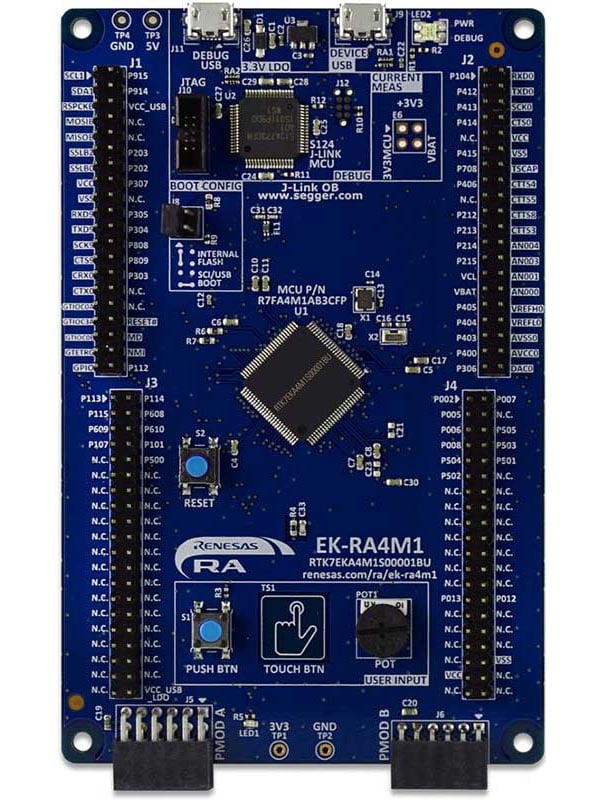
Features
- MCU Native Pin Access
- R7FA4M1AB3CFP MCU
- 48MHz, Arm Cortex®-M4 core
- 256kB Code Flash, 32kB SRAM
- 100 pins, LQFP package
- Native pin access through 4x 40-pin male headers
- MCU current measurement points
- Ecosystem & System Control Access
- USB Full Speed device
- 5V input through USB debug
- SEGGER J-LinkTM on-board programmer and debugger
- Debug modes
- Debug On-board (SWD) – via J-Link
- Debug Out (SWD) – via J-Link
- Debug in (SWD and JTAG)
- Two Digilent PmodTM (SPI and UART)
- User LED
- Mechanical user button
- Capacitive user button
- MCU boot configuration jumper
Applications
Design & Development
Software & Tools
Sample Code
Related Boards & Kits
Models
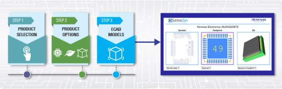
ECAD Models
Schematic symbols, PCB footprints, and 3D CAD models from SamacSys can be found by clicking on the CAD Model links in the Product Options table. If a symbol or model isn't available, it can be requested directly from SamacSys.
Support

Support Communities
Get quick technical support online from Renesas Engineering Community technical staff.


Videos & Training
Kickstart IoT and embedded systems development using Renesas EK-RA4M2 and EK-RA4M3, Evaluation Kits for RA4M2 and RA4M3 MCU Groups. Familiarize yourself with the kit architecture, key features, quick start example project, and many useful resources to begin innovating quickly.
News & Blog Posts
Blog Post
Mar 30, 2022
|
Blog Post
Jan 28, 2022
|
Blog Post
Nov 18, 2021
|
Blog Post
Nov 11, 2021
|
Certifications
The EK-RA4M1 kit meets the following certifications/standards. Refer to the EK-RA4M1 user manual for the disclaimer, precautions and more details on the certifications.
EMC/EMI Standards
- FCC Notice (Class A) – Part 15
- Innovation, Science and Economic Development Canada ICES-003 Compliance: CAN ICES-3 (A)/NMB-3(A)
- CE Class A (EMC Directive 2004/108/EEC)
- Taiwan Chinese National Standard 13438, C6357 compliance, Class A limits
- Australia/New Zealand AS/NZS CISPR 32:2015, Class A
Material Selection, Waste, Recycling, and Disposal Standards
- EU RoHS
- China SJ/T 113642014, 10-year environmental protection use period
Safety Standards
- UL 94V-0