Brushed DC Motor
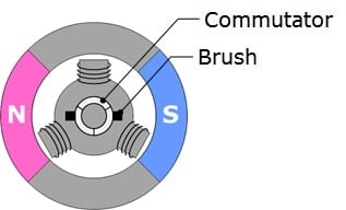
Since this type of motor is driven by a DC power supply, it is also called simply a DC motor. To distinguish it from a permanent magnet synchronous motor (brushless DC motor), here we will call it a brushed DC motor. Since it is comparatively economical and easy to drive, the brushed DC motor is used for a broad range of applications.
A brushed DC motor generates torque by mechanically switching the direction of current in coordination with rotation using a commutator and brushes. Shortcomings of a brushed DC motor include the need for maintenance due to wear down of the brushes and the production of electrical and mechanical noise. The PWM duty ratio can by adjusted using a microcontroller, etc. to change the applied voltage, thus allowing the speed of rotation and position to be controlled.
Applications
- Toys
- Power tools
- Automotive electronic components
Permanent Magnet Synchronous Motor (Brushless DC Motor)
Take away the commutator and brushes that are the shortcomings of the brushed DC motor and you have a permanent magnet synchronous motor (brushless DC motor).
Due to the lack of brushes, a brushless DC motor has excellent device life and low-noise characteristics. Also, it can achieve great efficiency, so it is used in a broad range of applications including energy-saving home appliances and long-running industrial applications.
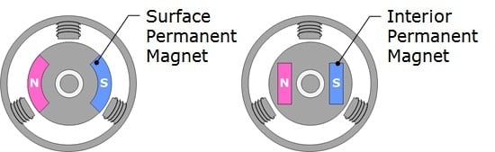
There are two major types of structure, differing by how the magnet is equipped on the rotor.
- Surface Permanent Magnet (SPM): This type has a permanent magnet affixed to the outside of the rotor, and magnetic permeability is constant through all positions.
- Interior Permanent Magnet (IPM): This type has a permanent magnet embedded inside the rotor, and since the magnetic permeability varies with position, reluctance torque can be used.
Since there is no structure for mechanically switching the direction of current, this needs to be performed electronically using an inverter circuit. By driving an inverter circuit using a microcontroller, etc., a three-phase alternating-current voltage is applied to the stator, generating a rotating magnetic field.
Driving waveforms can be divided into the following two main types.
- Trapezoidal wave drive: Drives by applying trapezoidal (rectangular) wave voltage.
- Sinusoidal wave drive: Drives by applying sinusoidal wave voltage in order to suppress the vibration, noise, and torque ripple which are issues encountered with trapezoidal wave drive. In many cases, vector control (fields oriented control) is use to control torque and phase in a linearly independent manner. Since torque is proportional to drive current, high-speed and high-precision position and speed control is possible by adding position and speed sensors.
In order to drive efficiently, it is necessary to detect the rotor (magnet) position. Hall sensors, encoders, and resolvers are used for detecting position. Due to temperature limitations of sensors and cost considerations, there are cases where rotor (magnet) position is estimated from three-phase current or induced voltage without using sensors (sensorless position estimation).
In general, industrial systems mainly use a sensor method and home appliance systems use a sensorless position estimation method.
Applications
- Air conditioners
- Washing machines
- Refrigerators
- Power tools
- Servos
- Robots
- Compressors
- Hard disk drives (HDD)
- Automotive electronic components
Three-Phase Induction Motor
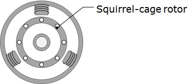
A three-phase induction motor is an induction motor driven on a three-phase alternating-current power source. A rotating magnetic field is produced by passing a three-phase alternating current through a stator, and an induced current is generated in the rotor by electromagnetic induction. This rotating magnetic field and induced current generate an electromagnetic force, which causes the rotor to rotate. Since the magnetic field needs to move in respect to the rotor in order to generate an induced current, the speed of rotation of the rotor is always slower than the synchronous speed of the rotating magnetic field. The difference between the frequency of the rotating magnetic field and the frequency equivalent to the speed of rotation is called the slip frequency. The generated torque is proportional to the slip frequency.
The structure of a three-phase induction motor is simple and sturdy. Because it is easy to use for large power motors and has relatively good efficiency, it is often used in industrial segments. However, due to the aforementioned slip frequency, it is unsuitable for position control.
In many cases, the three-phase alternating-current used at factories and so on is input directly to drive the motor at a constant speed. For adjustable-speed energy-saving applications that value efficiency, the motor can be inverter driven to control torque and speed of rotation.
Applications
- Industrial equipment
Single-Phase Induction Motor
Single-phase induction motors are a type of induction motor which as the name implies operate on a single-phase alternating-current power source. Since self starting is not possible with single-phase alternating current, the motor needs a way to start.
Single-phase induction motors can be divided into the following three main types, depending on the way they start.
- Capacitor: A capacitor splits phases to produce a two-phase alternating current to obtain a starting torque.
- Split Phase: A starter coil with low inductance is used to obtain a starting torque.
- Shaded Pole: A shaded pole produces an induced current, which is used to obtain a starting torque.
In many cases, the single-phase alternating current used in homes and so on is input directly to drive the motor at a constant speed. The AC voltage phase can be controlled using a triac to control the speed of rotation.
Applications
- Refrigerators
- Fans
- Vacuum cleaners
- Compressors
Stepper Motor
A stepper motor rotates the position of the rotor in a step-like fashion by switching the voltage pattern that is applied to a stator winding. Because the number of times the voltage pattern switches and the angle of rotation of a voltage pattern are in a precise proportion, the position can be controlled without any feedback. Shortcomings of a stepper motor include small torque, inability to handle sudden load changes, and susceptibility to vibration which reduces efficiency.
Stepper motors can be divided into the following three main types.
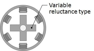
- Variable Reluctance (VR): Also called switched reluctance motor (SR motor). It is low cost because there is no magnet, but the disadvantage is poor efficiency.
- Permanent Magnet (PM): Since a permanent magnet is used, torque and efficiency are relatively high. Also, the position can be held even when the current is not flowing.
- Hybrid (HB): Combines VR and PM types for a motor with good resolution and relative torque and efficiency.
There are the following four main types of driving methods.
- Single-phase excitation: Drives by sending current through any single-phase winding, in order.
- Two-phase excitation: Drives by sending current through any two-phase winding, in order.
- Single-to-two-phase excitation: Combines single-phase excitation and two-phase excitation to drive in double the step angle.
- Microstep: Drives at a high-resolution step angle by sinusoidally changing the amount of current sent to each phase.
Applications
- Office automation equipment
- Cameras
- Industrial equipment