Overview
The GR-SAKURA board features the RX63N MCU and offers an Arduino compatible board footprint and a C++ template and libraries. The GR-SAKURA board is available in a standard version and full-featured version.
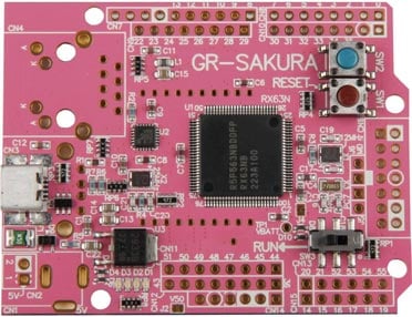
GR-SAKURA
Renesas' 32-bit RX63N Group MCU (R5F563NBDDFP) is on-board and Arduino UNO compatible pin-headers are ready for shields.
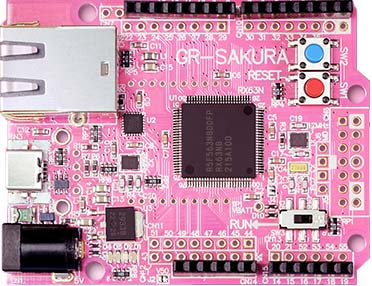
GR-SAKURA-FULL
Full version board has a LAN connector (RJ-45), USB host connector, DC power supply jack, and memory card shell.
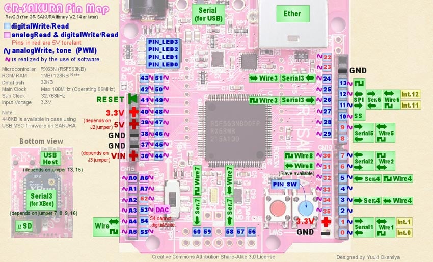
GR-SAKURA Pin Map
Detailed Specification
Microcontroller
RX63N (R5F563NBDDF P 100-pin QFP)
ROM/RAM
1MB/128KB
Data Flash
32KB
Frequency
96MHz (using external 12MHz XO)
Sub Clock
32.768kHz
Operating Voltage
3.3V
Board Function
USB host/peripheral (exclusion), Ethernet, Micro SD jacket, XBee I/F, JTAG I/F, DC power jack (5V), user switch, reset switch, Arduino shield I/F, user LED, programmable like USB mass storage
Resources
Schematic/Design
- gr-sakura-schematic-notes-20190917 (PDF)
- BOM List
- Layout
Sketch Reference
- GR-SAKURA Sketch Reference
How to Program
- GR-SAKURA Sketch on Web compiler
- GR-SAKURA Sketch on IDE for GR
Project File for e2 studio
Project file for sketching in Eclipse-based development environment e2 studio. For downloading and installing e2 studio, please refer to the e2 studio product page.
- Click to download. Import the archive file (zip) as an existing workspace from the menu 'File' -> 'Import' in e2 studio.
GR-SAKURA Sketch v223a Project File (ZIP)
Note: This is a project exported in e2 studio version 7.6.
Technical Support
- E-mail: gadget_renesas@lm.renesas.com
