Essentials of Microcontroller Use Learning about Peripherals: 6 of 6
In Part 5 - Programming (Session 1 of 2), we looked at how program code is stored in the CPU's address space, and at how vector tables are used to tell the CPU where to find the execution start locations within that space. In this second part, we look at how the CPU navigates through programs and interrupts.
Program Counter: Navigating Through the Code
A program consists of a series of instructions (the program code), stored more or less in order of intended execution. Before it can be executed, the program code must be loaded into some address space within internal RAM (as explained in the previous session). If we assume that each address within that space holds exactly one instruction and that all instructions execute in order, then the program flow is as follows: The CPU fetches and executes the instruction at the first address of the memory space (say, an instruction to set a particular value into an internal register), then fetches and executes the instruction at the next higher address, and so on.
How does the CPU know the sequence in which to execute instructions? The CPU has a special-purpose register called a program counter(PC) that points to the address of the next instruction to be executed. As each instruction is executed, the PC value is updated to point to the address of the next instruction.
Most of the time, the PC is updated by adding 1 to its value, so that it now points to the next address in the memory space; in other words, so that the instructions are executed in the order in which they are stored. This flow is illustrated in Figure 1. At step (1), the CPU is executing the instruction it fetched from address 1000h. As this execution completes (step (2)), the PC value automatically advances by 1. When ready for the next instruction (at step (3)), the CPU reads the PC and sees that the next address is 1001h, so it fetches the instruction at 1001h and executes it.
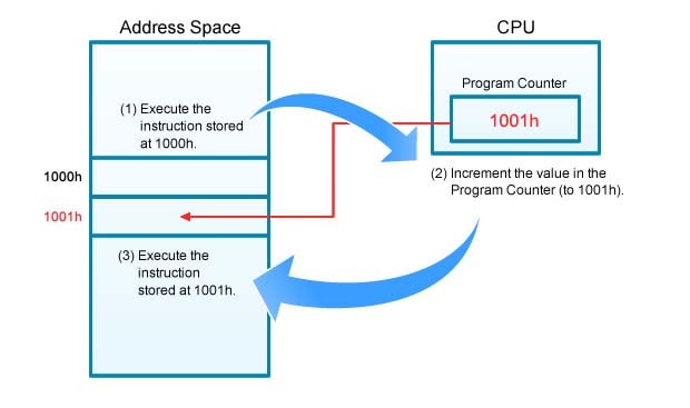
Figure 1.Program Counter
Where does the CPU go for its first instruction immediately after power on (or after a reset)? The answer: Immediately upon power-on (or reset), the CPU fetches the start-address-value from its predetermined location in the vector table (see Session 1 of 2, Fig. 2), and writes this value into the PC.
Address spaces and vector tables were covered in Part 5 - Programming (Session 1 of 2).
Branching Instructions
Instructions are not always executed in sequence, however; there are places where the CPU will encounter a branch instruction that tells it to jump to some other address for the following instruction. The CPU responds to the branch instruction by loading the indicated address value into the PC. This becomes the address the CPU will fetch next, when it is ready for the next instruction.
Figure 2 shows how a branch instruction works. In this example, we assume that the instruction in address 1000h is a branch instruction that tells the CPU to jump to address 1100h for the next instruction. Just before this example begins (not shown), the PC value is 1000h, so the CPU fetches and executes the instruction at 1000h. Because this instruction tells the CPU to jump to 1100h, the CPU writes 1100h into the PC. When the CPU is ready for the next instruction, it reads 1100h from the PC and then fetches and executes the instruction at that address.
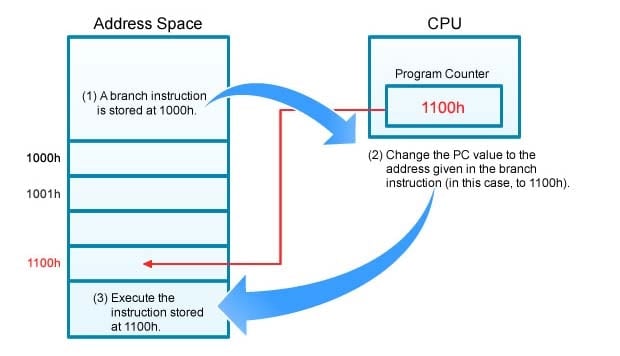
Figure 2,Branch Instrunction
Various types of branch instructions are in use. Many of these implement relative jumps: Instead of loading the PC with an absolute address, they tell the CPU to add or subtract a certain value from the PC's current value; this tells the CPU to jump forward or backward by some specified distance (some specified number of addresses) to get to the next instruction.
The Stack—A Special Holding Area for Data
Because the CPU may not have enough internal registers to hold all the data it needs when executing a program, it is sometimes necessary to move some data into a temporary storage area and then retrieve it later. The term stack refers to a special data structure that is widely used for this purpose. A stack is a LIFO (last-in first-out) structure; items are placed (pushed) onto the top of the stack in some predetermined order, and then retrieved (popped) from the top of the stack in the reverse order. (The term stack probably originated as a reference to the spring-supported plate stacks used in diners and family restaurants; clean plates are "stored" onto the top and then taken off the top as needed.)
A stack starts at some designated address in memory; it then grows as items are added, and shrinks back as items are removed. Since each operation involves either placing an item on the top of the stack or else taking it off the top, it is important to keep track of where the top is located at each moment. The CPU has a special-purpose register for this: the stack pointer (SP), which always holds the address value of the current top-of-stack. The SP value automatically increases and decreases as items are added and removed.
For more information about special-purpose registers, see Introduction to Microcontrollers - Part 1.
When it is time to place an item on the stack, a PUSH instruction causes the CPU to place the item at the top of the stack—that is, in the address given by the address value stored in the SP. At about the same time, the CPU also changes the SP value by 1, so that it now points to the new top of stack. Note that, since stacks usually begin in high memory locations and "grow" into lower memory locations, the SP value moves in the opposite direction of growth: the value goes down by one each time a new item is added, and goes up by one when the top item is popped off.
Figure 3 illustrates the flow. At step (1), the CPU pushes a data item onto the stack, at the address given by the SP. At step (2), the CPU decrements the SP value, so that at step (3) the SP is pointing to the new top-of-stack.
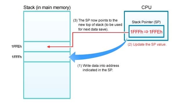
Figure 3.Pushing Data Onto the Stack
When it is time to retrieve an item from the stack, a POP instruction is used. Figure 4 shows the flow. At step (1), the CPU increments the SP value (this makes the stack 1 item shorter). At step (2), the CPU retrieves the item. And at step (3), the SP is now pointing at the new top.
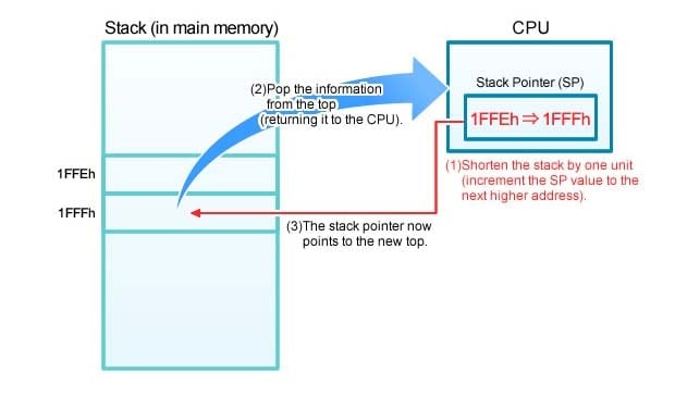
Figure 4.Popping Data off the Stack
Like everything else, stacks have limited capacity. In particular, a stack can never grow larger than the size of installed RAM. A stack overflow—caused by attempting to place more items onto the stack that it will hold—will usually cause the current program to crash.
Review of Interrupt Processing
This is our final session in our series covering the Essentials of MCU Use: Learning about Peripherals. Let's review some of what we've learned about general MCU processing.
Figure 5 illustrates the interrupt processing flow. Remember that an interrupt is used to suspend a currently executing program so that an entirely different program can be loaded and executed; after the latter program (the "interrupt program") is completed, the previous program resumes at the point where it was interrupted.
Figure 5 shows the flow of an interrupt generated by a watchdog timer (WDT)—one of the MCU's built-in peripherals. A WDT remains quiet so long as the MCU is running normally. It will execute an interrupt, however, in the event that the currently running program hangs and causes the whole system to essentially freeze. The purpose of the interrupt is to invoke an interrupt program that will close the hung program and return the system to normal.
For a more detailed illustration of the interrupt processing flow, see Part 4 - Interrupts of this series.
For more information about WDTs, see Part 2 - Timers of this series.
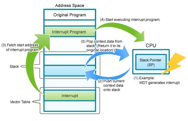
Figure 5.Interrupt Processing Flow
The flow is as follows.
- The CPU receives the interrupt.
- The CPU saves the context (the execution status) of the currently running program (so that it can, if possible, resume execution after interrupt processing is completed). In particular, it saves the necessary data onto the stack, starting from the address indicated by the SP. The data to be saved includes the following: the PC value (the current location in the interrupted program, so that processing can be resumed from the same place); the current values of the CPU's internal registers; and related work data.
- The CPU loads the start address for the interrupt program into the PC, so that it will know where to go to fetch the first instruction of this program. The CPU gets this start-address value from a predetermined location in the vector table—a table which holds a variety of start addresses. For example, the table holds start addresses for timer interrupts, NMI interrupts, and various types of error handling. For more about the vector table, see Figures 2 and 3 in Part 1 of this lesson.
For more information about vector table processing, see Part 5 - Programming (Session 1 of 2). - The CPU now starts running the interrupt program, starting from the new address in the PC. A similar process occurs in the event of other errors, as well, where it is necessary to start a corresponding error routine. Typical errors include an attempt to divide by 0, and attempts to access non-existing memory space. In each case, the CPU will save the current context, then load the start address for the corresponding error-processing routine, then process the error, and then pass control back to the interrupted program or else to some other process.
- In the case of a WDT interrupt, the CPU will shut down the interrupted program (because the program had hung) rather than return control to it. With a typical periodic interrupt, however, the CPU—after completing the interrupt processing—will reload the interrupted program's context from the stack, restore the PC to its value at the time of the interrupt, perform a number of other housekeeping tasks, and then resume the interrupted program from where it left off.
At the start of an interrupt, either the external interrupt signal or the CPU itself generates the instructions necessary to save the current program context to the stack. When interrupt program processing is completed, a single "return" instruction tells the CPU to pop and reload the saved context and return processing to where it left off. The programmer does not need to worry about managing the sequence in which the stacked data is restored; the CPU itself is aware of the order and restores the entire context correctly in response to the single "return" command.
Together with Part 5 - Programming (Session 1 of 2), we look at how the CPU executes a program. Interrupt programming is based on the same internal operating principles: the interrupt program code is placed at a certain location in the address space; a specific location in the vector table stores the address value that tells the CPU where to find the first instruction for this program; a stack is used to save context when switching programs and then to reload that context when switching back; and so on. It can be both challenging and satisfying to write programs that closely control all aspects of MCU operation so as to bring out the full potential of the MCU.
This is the final session in this series covering "Essentials of MCU Use: Learning about Peripherals" We tried to keep each session focused on basics, as we wanted to provide all readers—including beginners—with a reasonable understanding of how things work. We invite you to return to and review this material as often as you like.
Module List
Support

Support Communities

