Overview
Description
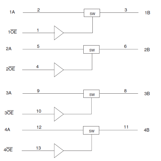
The CBTLV3126 features four independent switches. Each switch is enabled when the associated output-enable (OE) input is high.
To ensure the high-impedance state during power up or power down, OE should be tied to GND through a pulldown resistor; the minimum value of the resistor is determined by the current-sinking capability of the driver.

Comparison
Applications
Design & Development
Models
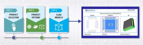
ECAD Models
Schematic symbols, PCB footprints, and 3D CAD models from SamacSys can be found by clicking on the CAD Model links in the Product Options table. If a symbol or model isn't available, it can be requested directly from SamacSys.
Product Options
Applied Filters: