1. About HW-RTOS
HW-RTOS (hardware real-time operating system) is a real-time OS implemented in hardware, and is a proprietary technology of Renesas Electronics. HW-RTOS supports roughly 30 APIs, which are all implemented through hardware. The hardware implementation offers an extremely high level of real-time performance compared to conventional software RTOS. Specifically, HW-RTOS achieves.
- Fast API execution with little fluctuation
- Low interrupt latency with low jitter
- Very short interrupt disable period
Unlike with conventional software RTOS, worst case execution time can be guaranteed. This facilitates real-time system design.
HW-RTOS offers not only a high-performance RTOS, but also sufficient functionality as an RTOS for embedded systems. HW-RTOS supports the following APIs.
- Semaphore
- Event flag
- Mail box
- Lock CPU and disable dispatch
- Sleep / wakeup
- Release waiting
- Rotate ready queue
- Change priority
2. Invoking an API
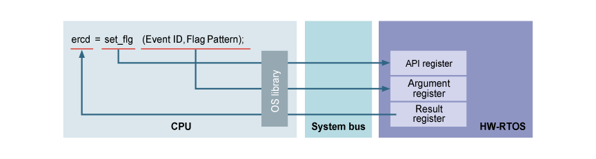
HW-RTOS is implemented as one of the peripheral modules on the system bus. As shown in the following figure, HW-RTOS has an API register, argument register, and result register. Renesas has prepared an OS library for handling these registers. Users can use the OS library to easily invoke API calls just like a conventional software RTOS.
As shown in the following figure, when a set_flg API call is invoked, the OS library writes arguments to the argument register and the type of API to the API register. When the HW-RTOS receives these, it executes the API and writes the return value to the result register. The OS library reports the return value to the invoking application.
Task switching may be required as a result of API execution. At such times, HW-RTOS indicates that a task switch is required and writes the ID of the next task that should be executed to the result register to convey this information to the OS library. The OS library executes a context switch according to this information.
3. Tick offloading
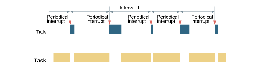
An RTOS measures time using software. For example, when a task sleeps and activates again one second later, the RTOS needs to measure this one second. Software for measuring time is activated periodically for this purpose. This is called the tick process. As shown in the figure, a periodical interrupt is required in order to activate tick process.
Although the tick is an indispensable function, it has the following three disadvantages. Firstly, as the below figure shows, the application is stopped periodically, so CPU usage efficiency is decreased. Secondly, since the ticks are performing an extremely critical process, all interrupts are disabled during the process execution. Thus, this has a negative effect on interrupt response time. Thirdly, because the tick process needs to be implemented by software, the tick interval cannot be extremely short — in other words it can be said that highly precise time management is not possible.
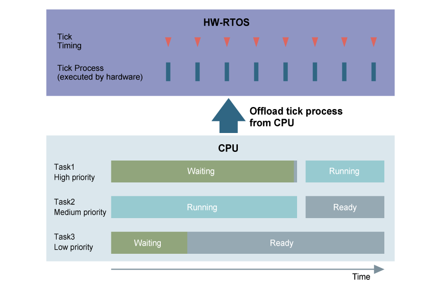
On the other hand, HW-RTOS implements the tick process completely in hardware. This function is called tick offloading. The tick process is carried out inside HW-RTOS. Therefore, there is no need for a periodical interrupt for ticks, and no need for the CPU to carry out the tick process. As shown in the figure, the CPU is free to run application software at all times. The only time this is stopped is when a context switch is carried out by a timeout. Furthermore, because the tick process is performed at very high speed, the tick interval can be shortened. For the reasons mentioned above, tick offloading can provide the following advantages over conventional software.
- No drop in CPU efficiency caused by tick process
- No interrupt disable period caused by tick process
- Large improvement in tick precision
4. Hardware ISR (HW ISR)
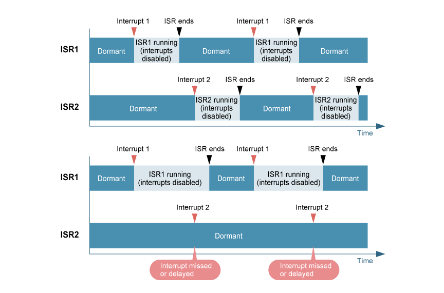
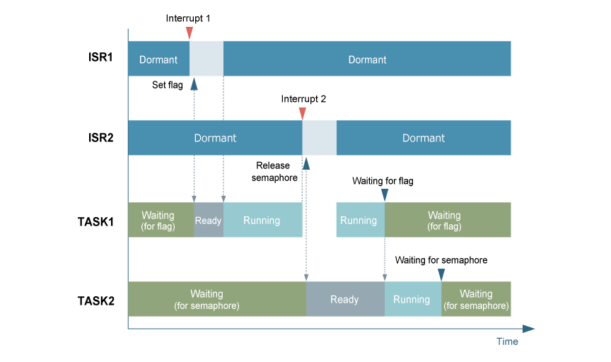
When an interrupt occurs, an interrupt service routine (ISR) is activated. In general, interrupts are disabled while an ISR is executing. In the upper part of the following figure, ISR1 and ISR2 activate alternately according to the type of interrupt.
If processing of ISR1 is prolonged, the other interrupt will be missed or delayed as shown in the lower part of the figure. Interrupts being missed or delayed is undesirable for real-time systems.
In general, the following method is used to avoid such issues.
As shown in the following figure, the processing of ISR1 is handed over to task 1, and the processing of ISR2 is handed over to task 2. Since interrupts are not disabled for tasks, other interrupts will not be affected.
The method used to hand over processing is as follows. Task 1 waits a flag. When the first interrupt (interrupt 1) occurs, ISR1 executes the API to release the waiting state of task 1.
This method minimizes the effect of interrupt processing on other interrupts.
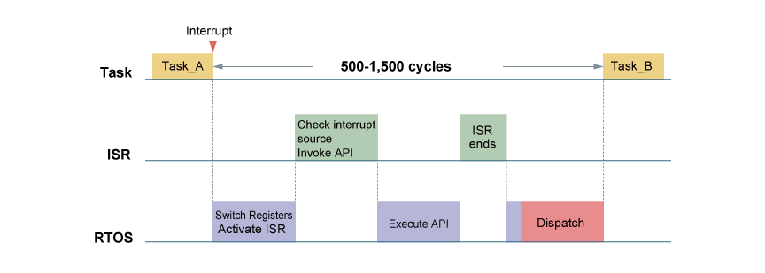
Let's look at how the ISR executes the API when an interrupt occurs in a little more detail. This is shown in the next figure. Let's suppose that an interrupt occurs while Task_A is running.
- The RTOS switches CPU registers and activates the ISR.
- The ISR checks the interrupt source and invokes the API that corresponds to the interrupt.
- The RTOS executes this API.
- When the API finishes, the ISR also ends.
- As a result, the ready queue is changed. If Task_B, to which ISR processing has been handed over, has a higher priority than Task_A, a dispatch is executed and Task_B will run.
However, the above process is quite complicated, and usually takes about 500 to 1,500 cycles.
On the other hand, if HW-RTOS is used, since all the RTOS processing shown in the figure except for the dispatch process is implemented in hardware, the processing is very fast.
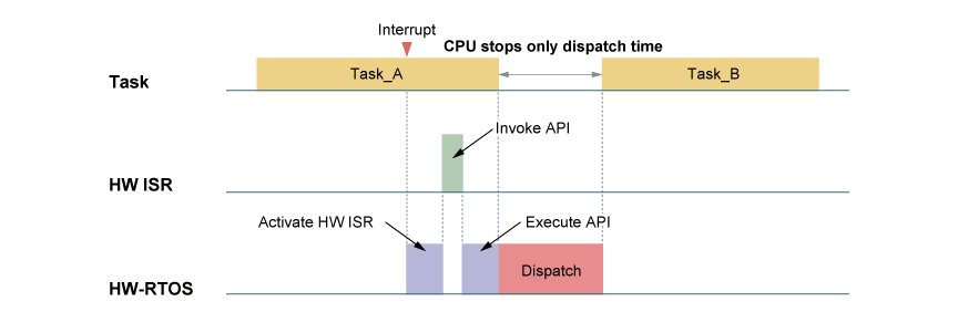
HW-RTOS accelerates this even further. That is, it accelerates the ISR process. An ISR simply invokes the API that corresponds to the interrupt source. By implementing this portion into hardware, it is accelerated. This implementation is called a hardware ISR (HW ISR).The following figure shows the timing chart for the HW ISR.
- An interrupt occurs and HW-RTOS commences operation. HW-RTOS activates the HW ISR.
- The HW ISR invokes the API that corresponds to the interrupt.
- HW-RTOS executes the invoked API.
- As a result, the ready queue is changed. If Task_B, to which ISR processing has been handed over, has a higher priority than Task_A, a dispatch is executed and Task_B will run.
Notice that the CPU is free to continue processing Task_A while HW-RTOS and the HW ISR are processing. The CPU only stops during the task switching period.
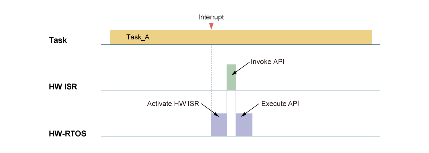
The next figure shows an example of Task_B is in ready state at the end of API execution, but Task_B priority is lower or equal compare with Task_A priority, when Task_B has been handed the ISR processing. In this case, since Task_A has the higher priority there is no need to switch tasks, so Task_A continues processing. Even if an interrupt occurs, it causes zero CPU overhead. This is amazing.
By using an HW ISR, you gain the following benefits:
- Greatly reduce CPU overhead during interrupts
- Greatly shorten interrupt disable period
- Greatly reduce the number of context switches
It is possible to replace almost all interrupts in a regular system with HW ISR. For processes that you want to perform quickly, you can simply raise the priority of the task that is activated by the HW ISR. Of course, HW-RTOS can also supports conventional ISR.
5. HW-RTOS performance
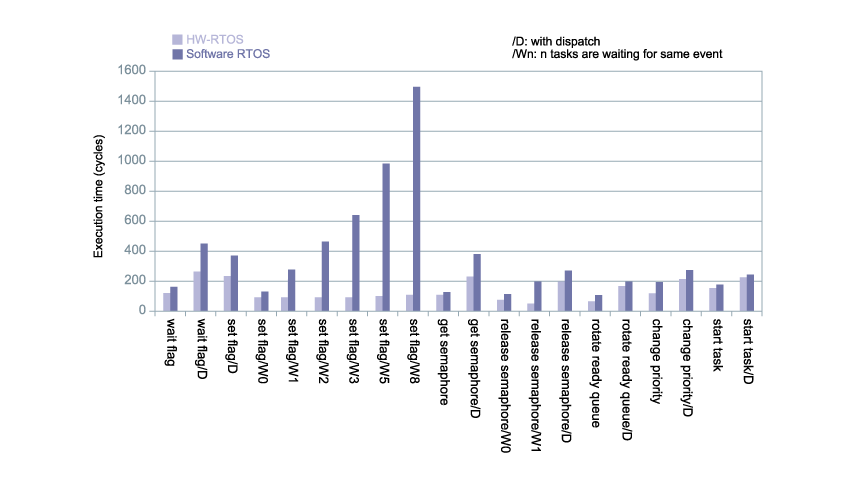
The following figure shows API execution time. Execution time of a conventional software RTOS is shown in dark purple and HW-RTOS in light purple.
Not only does HW-RTOS have short execution time than a software RTOS, it also does not fluctuate much.
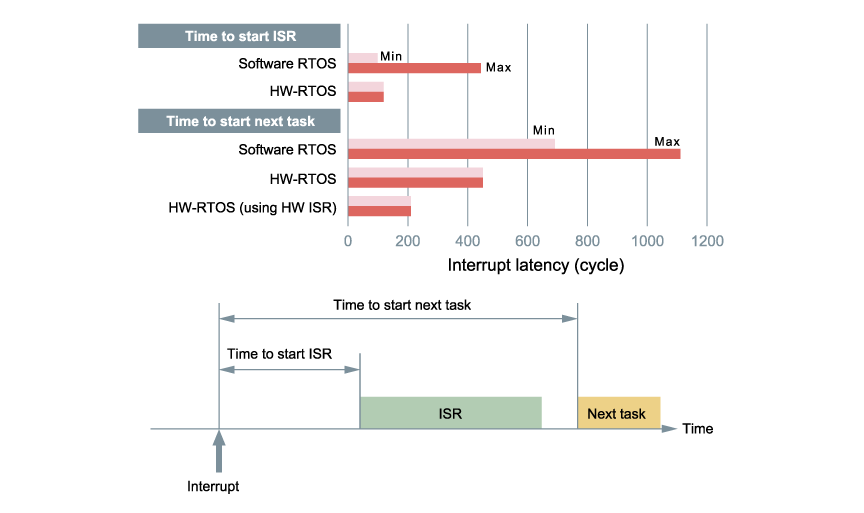
The next figure shows interrupt latency. Time was measured from the occurrence of an interrupt until the activation of ISR and until the activation of the next task. Interrupt latency is high with high jitter in a software RTOS but is low latency with low jitter in HW-RTOS. You can see a great improvement in performance when an HW ISR is used.
6. Network and RTOS
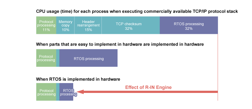
When TCP/IP is implemented in a CPU for an embedded system, unlike a CPU for a personal computer, it is very difficult to achieve high throughput. The upper part of the following figure shows a profile of transmission and reception using a commercially available TCP/IP protocol stack. Only 11% of CPU processing time is spent on complicated protocol processing. The rest of the time is spent on memory copy, rearranging headers, performing TCP checksum, and RTOS processing. Of these processes, memory copy, header rearrangement, and TCP checksum are easy to implement in hardware. The middle part of the following figure shows the profile for this implementation. However, RTOS processing still has a high overhead. Since protocol processing like TCP/IP has multiple tasks, task switching is required every time a packet is sent or received. Multiple API calls are also needed. That is why the profile has a high overhead by RTOS. HW-RTOS solves this issue. By using HW-RTOS, you can greatly reduce the load on the CPU as shown in the lower part of the figure. That is to say, you can achieve high network performance using low-end CPUs as used in embedded systems. Furthermore, if not so high network throughput is needed, a low system clock rate can be used to greatly reduce power consumption.
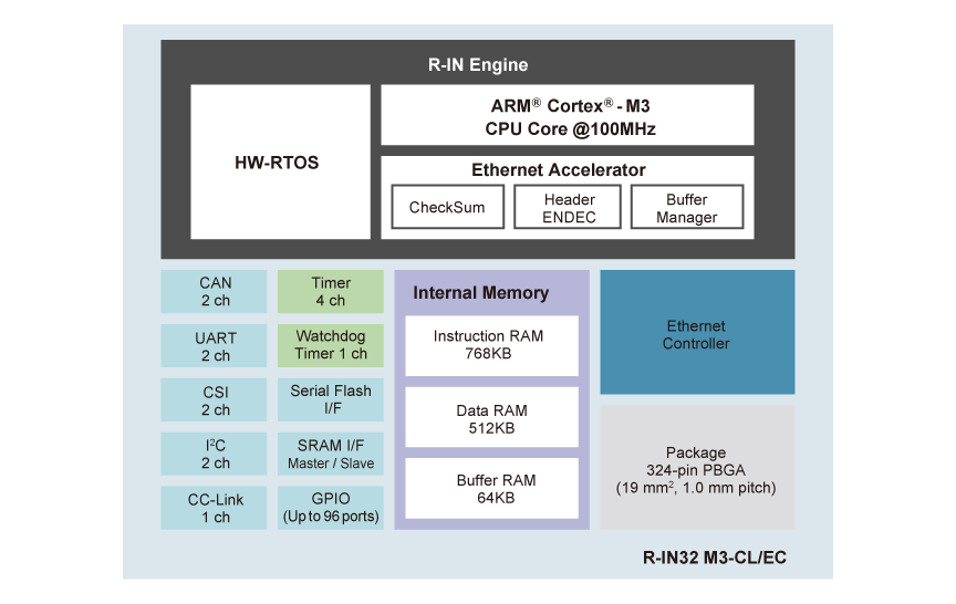
The next figure shows the block diagram for the R-IN32M3. The R-IN engine consists of HW-RTOS, a Cortex®-M3 core, and an Ethernet accelerator. The Ethernet accelerator is the hardware that accelerates the aforementioned memory copy, header rearrangement, TCP checksum processes. By using the R-IN engine it is possible to accelerate TCP/IP and other network protocol processing. The R-IN engine is included in all devices in the R-IN32 Series and the RZ/N1 Series, and in some RZ/T1 devices.
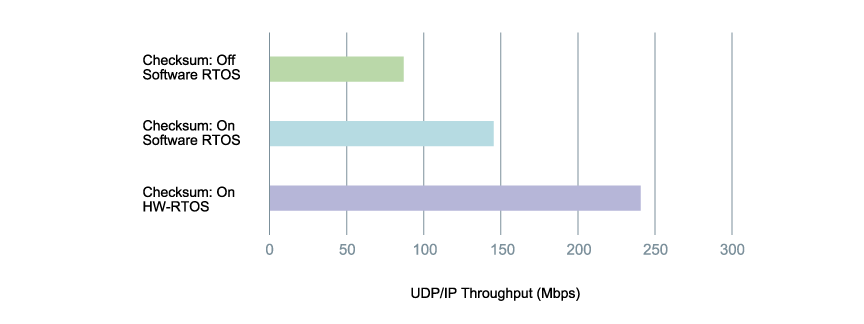
This below figure shows the measured throughput of UDP/IP implemented in the R-IN32M3. The operating clock is 100 MHz and the Ethernet frame length is 1500 bytes. The bar at the top shows throughput of UDP checksum performed by software in a software RTOS implementation with HW-RTOS turned off. The middle bar shows the throughput of a hardware-implemented checksum, and the bottom bar the throughput with HW-RTOS turned on. As you can see, the R-IN engine with HW-RTOS is very effective for accelerating network protocol processing.
Support

Support Communities


