
The RX-T MCU series has been implemented by many manufacturers of air conditioner outdoor units and industrial inverter applications and has been highly valued in the inverter control field. Additionally, in recent years, it has been increasingly adopted in power control applications such as Uninterruptible Power Supply (UPS), solar inverters, and electric vehicle chargers to name a few. This time, I will introduce how to design power supply control with MCUs, taking the UPS as an example of a power supply control application.
The UPS has the three below functions and is helpful for showing the basics of power supply control with MCUs.
UPS functions
- AC-DC converter with Power Factor Correction (PFC) (hereafter, AC-DC): converts line power to DC
- DC-DC converter (hereafter, DC-DC): converts high voltage DC to low voltage DC to charge batteries or discharges batteries to convert low voltage DC to high voltage DC
- DC-AC inverter (hereafter, DC-AC): converts DC to AC for equipment with sockets to power electrical devices.
These power functions could be controlled with a single RX MCU by utilizing the below common peripherals of RX. Though the MCU used this time is the RX66T series, other RX series with these functions such as the RX72T and the RX24T can reproduce all or part of these power supply control functions.
RX family peripherals used:
- PWM output timer (MTU3d, GPTW)
- 12-bit A/D converter (S12ADH)
- Port output enable (for PWM output emergency stop) (POE3B)
- Comparator (for overcurrent detection) (CMPC)
- 12-bit D/A converter (for reference voltage of comparator) (R12DAb)
These functions, which are ideal for inverter control, enable configuring the power supply control’s circuit as below.
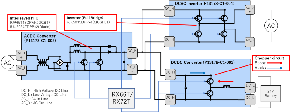
UPS circuit
- AC-DC
- The output DC has a small current ripple since the interleaved PFC is driven in current continuous mode, often used in motor control equipment, by the complementary PWM output (carrier frequency 60KHz) of MTU3
- DC-DC
- By driving a chopper circuit that combines a boost and buck circuit by the complementary PWM output (carrier frequency 40KHz) of MTU3, batteries are charged with AC-DC power supplies (buck mode), or the battery power is discharged and supplied to DC-AC (boost mode) without voltage variation.
- DC-AC
- By switching power devices of a bridge circuit, like a motor control circuit, by the complementary PWM output (carrier frequency 20KHz) of GPT, the sine wave of 110V at 50Hz is generated. The vector control algorithm is applied so that the sine wave is outputted without distortion.
By combining these circuits, the configured UPS can achieve a power efficiency of up to 98% equivalent to one with dedicated ICs. Thus, in addition to dedicated products such as AC-DC PFC ICs and DC-DC power ICs, RX MCUs become a good candidate for power supply control, offering our customers wider options and allowing them to pick the most suitable product for the job.
This time, I’ve introduced the feasibility of power supply control (UPS) as an application of inverter control. We will keep developing products to meet our customers' needs and contribute to their innovations.
Please stay tuned for the further expansion of the RX family!
For detailed information on the UPS described in this blog, please refer to the UPS Application Note.
For the typical system configuration of an Uninterruptible Power Supply (UPS), please refer to the UPS Winning Combination.
For detailed information on the RX66T, please refer to the RX66T product page.