Overview
Description
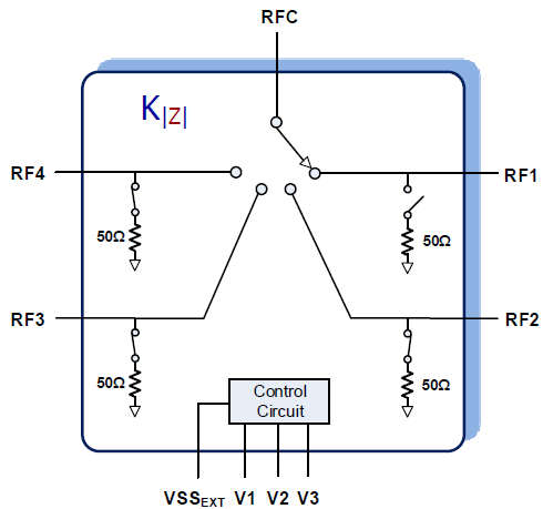
The F2914 is a high reliability, low insertion loss, 50Ω SP4T absorptive RF switch designed for a multitude of wireless and other RF applications. This device covers a broad frequency range from 50MHz to 8000MHz. In addition to providing low insertion loss, the F2914 also delivers excellent linearity and isolation performance while providing a 50Ω termination to the unused RF ports. The F2914 also includes a patent-pending constant impedance (Kz) feature. Kz improves hot switching ruggedness, minimizes LO pulling in VCOs, and reduces phase and amplitude variations in distribution networks. It is also ideal for dynamic switching/selection between two or more amplifiers while avoiding damage to upstream/downstream sensitive devices such as PAs and ADCs.
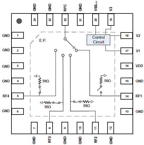
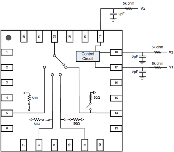
The F2914 uses a single positive supply voltage supporting three logic control pins using either 3.3V or 1.8V control logic. Connecting a negative voltage to pin 20 disables the internal negative voltage generator and becomes the negative supply.
Features
- Four symmetric broadband, absorptive RF ports
- Constant Impedance, Kz, feature
- High-performance RF
- Isolation of 54dB at 2700MHz
- Insertion Loss of 1.15dB at 2700MHz
- High continuous RF CW Power Handling
- Selected RF path: 33dBm
- Terminated RF path: 27dBm
- High linearity:
- IIP2 of 114dBm
- IIP3 of 59.5dBm
- Single 2.7V to 5.50V supply voltage
- External Negative Supply Option
- 3.3V and 1.8V compatible control logic
- Operating temperature -40 °C to +105 °C
- 4mm x 4mm 24-pin QFN package
Comparison
Applications
Documentation
Featured Documentation
Log in required to subscribe
|
|
|
|
|---|---|---|
| Type | Title | Date |
| Datasheet | PDF 800 KB | |
| Guide | PDF 2.24 MB | |
| Application Note | PDF 432 KB | |
| Product Brief | PDF 438 KB | |
| Product Change Notice | PDF 36 KB | |
| Product Brief | PDF 252 KB | |
6 items
|
||
Design & Development
Boards & Kits

Evaluation
F2914EVBI
Active
Evaluation Board for High Reliability SP4T Absorptive RF Switch
The F2914EVBI is a fully populated evaluation board which allows the customer to easily evaluate the F2914 RF switch.
“Thru” calibration connectors are conveniently located on the eval board to simplify the calibration process prior to making any RF measurements. Each RF port (RF1, RF2, RF3,...
Recommended Documents:
Models
ECAD Models
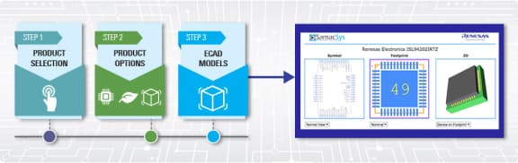
Schematic symbols, PCB footprints, and 3D CAD models from SamacSys can be found by clicking on the CAD Model links in the Product Options table. If a symbol or model isn't available, it can be requested directly from SamacSys.
Product Options
Applied Filters: