Overview
Description
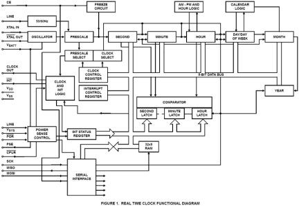
The CDP68HC68T1 Real-Time Clock provides a time/calendar function, a 32 byte static RAM, and a 3 wire Serial Peripheral Interface (SPI Bus). The primary function of the clock is to divide down a frequency input that can be supplied by the on-board oscillator in conjunction with an external crystal or by an external clock source. The internal oscillator can operate with a 32kHz, 1MHz, 2MHz, or 4MHz crystal. An external clock source with a 32kHz, 1MHz, 2MHz, 4MHz, 50Hz or 60Hz frequency can be used to drive the CDP68HC68T1. The time registers hold seconds, minutes, and hours, while the calendar registers hold day-of-week, date, month, and year information. The data is stored in BCD format. In addition, 12 or 24 hour operation can be selected. In 12 hour mode, an AM/PM indicator is provided. The T1 has a programmable output which can provide one of seven outputs for use elsewhere in the system. Computer handshaking is controlled with a wired-OR interrupt output. The interrupt can be programmed to provide a signal as the result of:
- An alarm programmed to occur at a predetermined combination of seconds, minutes, and hours.
- One of 15 periodic interrupts ranging from sub-second to once per day frequency.
- A power fail detect. The PSE output and the VSYS input are used for external power control. The CPUR output is available to reset the processor under power-down conditions. CPUR is enabled under software control and can also be activated via the CDP68HC68T1's watchdog. If enabled, the watchdog requires a periodic toggle of the CE pin without a serial transfer.
Features
- SPI (Serial Peripheral Interface)
- Full Clock Features
- Seconds, Minutes, Hours (12/24, AM/PM), Day of Week, Date, Month, Year (0 to 99), Automatic Leap Year
- 32 Wordx8-Bit RAM
- Seconds, Minutes, Hours Alarm
- Automatic Power Loss Detection
- Low Minimum Standby (Timekeeping) Voltage 2.2V
- Selectable Crystal or 50/60Hz Line Input
- Buffered Clock Output
- Battery Input Pin that Powers Oscillator and also Connects to VDD Pin When Power Fails
- Three Independent Interrupt Modes
- Alarm
- Periodic
- Power-Down Sense
- Pb-Free Available (RoHS Compliant)
Comparison
Applications
Documentation
|
|
|
|
|---|---|---|
| Type | Title | Date |
| Datasheet | PDF 1.04 MB | |
| End Of Life Notice | PDF 1.17 MB | |
| Price Increase Notice | PDF 257 KB | |
| Price Increase Notice | PDF 227 KB | |
| Product Change Notice | PDF 223 KB | |
| Product Change Notice | PDF 98 KB | |
| Product Change Notice | PDF 86 KB | |
| Application Note | PDF 554 KB | |
8 items
|
||
Design & Development
Models
ECAD Models
Schematic symbols, PCB footprints, and 3D CAD models from SamacSys can be found by clicking on products in the Product Options table. If a symbol or model isn't available, it can be requested directly from the website.

Product Options
Applied Filters:
