It’s time to build a Battery Management System (BMS) – but where to start? Every BMS is fundamentally a real-time data acquisition system that measures the individual battery cell voltages at regular time intervals. Ideally, the system also measures the battery current at the same moments, and less frequently, the battery temperatures. Collectively, the hardware and software necessary to perform these functions is the battery measurement subsystem. And the voltage, current, and temperature measurements are then processed in the higher levels of the BMS software (the application layer) to properly control the battery pack.
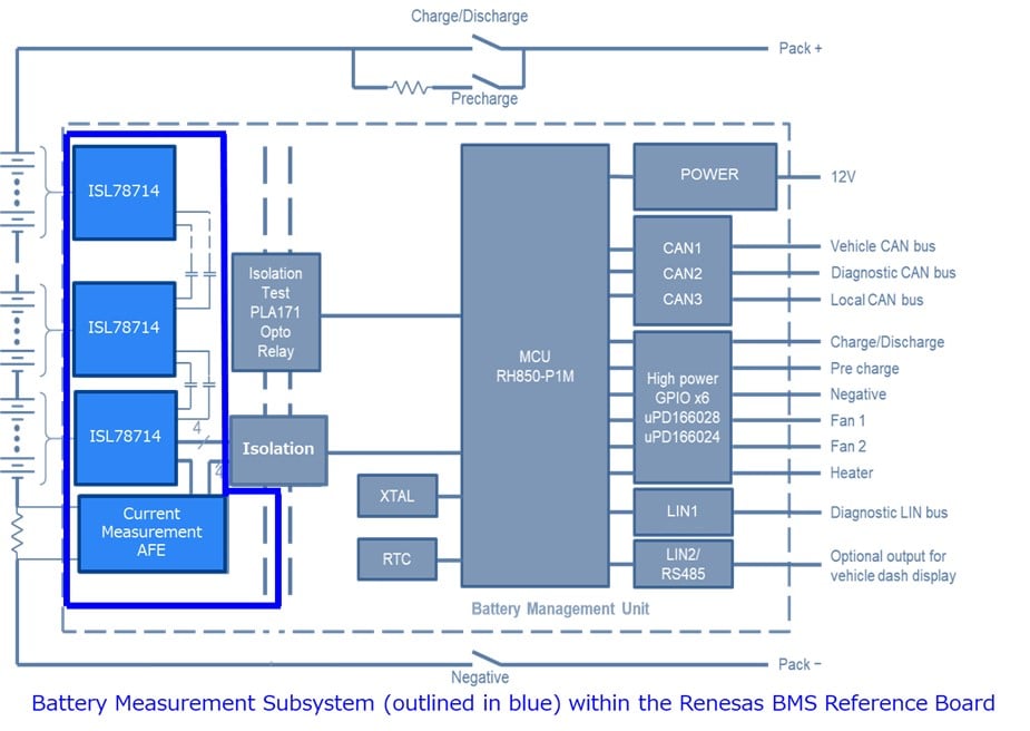
While OEMs often develop their own application software that optimizes the performance of their vehicles, all BMS systems begin with the same type of low-level software that interfaces to the cell sensing ICs, like the Renesas ISL78714. This foundational software is responsible for collecting the large number of periodic measurements (a typical electric vehicle might need to acquire a hundred individual cell voltages and a common battery current every 20mS, and a couple dozen temperature readings several times per second). And because these measurements are used for functionally safe vehicle control, many safety mechanisms must be executed regularly to assure their operational integrity.
Developing this low-level software requires significant resources, and for some xEV developers, the learning curve and effort to create the time-critical software represents a prohibitively high burden. So Renesas initiated a project with TATA Elxsi, a recognized automotive software and services provider, to create an AUTOSAR-compliant, ASIL-D certified, complex device driver (CDD) for the ISL78714. This driver fully integrates all the low-level cell voltage, battery current, and temperature measurement functionality, as well as all necessary safety mechanisms.
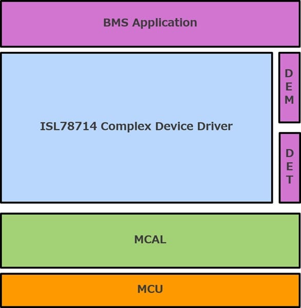
With the CDD, an entire battery measurement subsystem can be up and running after setting the necessary configuration parameters (number of battery cells, operating limits, etc). The architecture of the CDD allows the application software to step the measurement subsystem through the Power Up Initialization, Normal run, Sleep, Wakeup, and Shutdown states. An additional state, Command, can be entered by the application and will suspend the automated functionality of the CDD. In the Command state, the CDD APIs can be used by the application software to communicate directly with the individual ISL78714 devices, thus providing complete flexibility over their usage.
But the greatest benefit of the CDD, is its ability to offload the data acquisition process from the BMS application software. While running in its Normal state, the CDD will sample all the battery cell voltages and current at the required time intervals. And as this data is collected, a callback or polling mechanism may be used by the application software to receive the latest set of battery data.
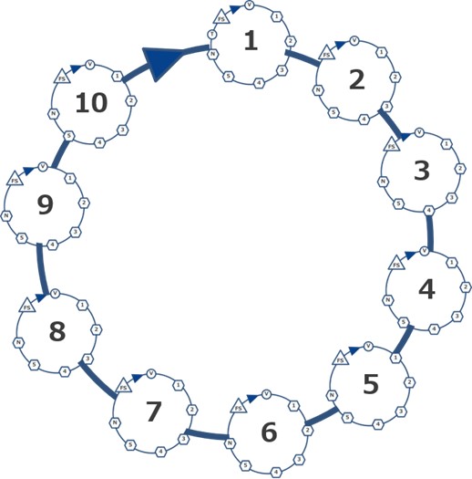
To achieve ASIL-D functional safety coverage, the CDD implements all 46 of the safety mechanisms outlined in the ISL78714 Safety Manual. The execution of these safety mechanisms is interleaved within the normal voltage, current, and temperature measurements; resulting in an architecture based on measurement sequences. Each measurement sequence, or loop, begins with a command to measure all cell voltages and current. The trigger for starting each sequence can be either a General Purpose Timer (GPT) or an OS cyclic task. The ultimate control over the sampling period will be determined by the selection of this trigger by the system designer, but once the event occurs the CDD will not introduce any additional timing variation in the execution of this first measurement action. At the end of each sequence, relevant safety mechanisms are executed.
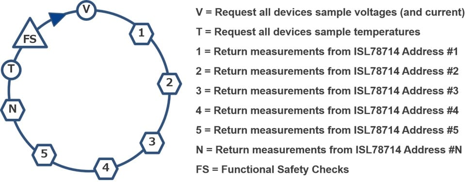
A total of ten measurement Sequences are used to complete all the BMS measurements and safety mechanisms. As the trigger for each sequence is periodic, all cell voltages and current will have been collected ten times, while the temperatures will have been collected once, with the resulting total time representing one Fault Tolerant Interval (FTI).
When it comes to measurements within a BMS, timing is everything. And the CDD manages that timing, while also saving development time. With respect to functional safety, the ISL78714 CDD was assessed by TUV SUD as ASIL-D for the Renesas BMS Reference Board. For customers interested in developing their own ISL78714 device driver, the CDD is available as sample code. And for customers who wish to integrate the driver in their own ASIL-rated BMS, TATA Elxsi is available to support their specific application of the CDD under authorization from Renesas.