Get to know this life changing technology: 2 of 5
The USB PD standard enables the power delivery of USB power up to 100W, sufficient to drive large devices such as laptops and monitors. This standard greatly increases convenience, with provisions included to ensure safety. Here we look at some of the technologies that underlie these capabilities.
New Capabilities
USB Power Delivery Revision 3.0 (below, “USB PD”) allows for delivery of power up to 100W through a single cable. The specification makes it possible to power multiple devices simultaneously, eliminating the need for a dedicated AC adapter for each device. It also provides two other important functionalities: FAST ROLE SWAP (FRS) allows devices to switch roles as power providers and power consumers; and PROGRAMMABLE POWER SUPPLY (PPS) makes possible for rapid charging without unnecessary heat. USB Type-CTM Authentication capability (below, “C- AUTH”) is another significant recent addition. Below, we look at USB PD features, and explain the new capabilities.
Not Just 5V Anymore
Conventional USB implementations can only provide a 5V power supply. But many digital devices require more than this. Higher voltages are needed to enable faster charging and to drive motorized appliances in particular. For this reason, USB PD adds support for 9V, 15V, and 20V (see Table 1), so as to work with a much wider range of devices. And while typical USB Type-CTM cable carries up to 3A current, USB Type-CTM cable which support USB PD is allowed to carry up to 5A—it means the maximum power is 100W.
| PD Power | Current at 5V (A) | Current at 9V (A) | Current at 15V (A) | Current at 20V (A) |
|---|---|---|---|---|
| 15W and under | check | |||
| 15W to 27W | 3A | check | ||
| 27W to 45W | 3A | 3A | check | |
| 45W to 60W | 3A | 3A | 3A | check |
| 60W to 100W | 3A | 3A | 3A | check* |
Table 1: Normative Voltages and Currents (Checkmark indicates that the current varies according to the PD Power.)
*Only when using 5A cable. Limited up to 3A when using 3A cable.
The convenience should not be sacrificed even when supporting multiple voltage levels. Suppose, for example, you want to power a device that operates on 12V at 2A (24W), and you’ve found an AC adapter rated at 27W. Since you don’t know the adapter’s output voltage capabilities, however, you can’t be sure it’s usable. USB PD addresses this issue through the use of “power rules” that dictate how compliant power sources must behave. Note that in the discussion below, “source” denotes the power supplier, and “sink” denotes the power consumer.
The relevant power rule, for the example mentioned above, requires that compliant devices be designed to guarantee operation in cases where the source power (W) ≥ sink power (W). In this example, the sink requests 12V from the adapter—but the adapter has no obligation to support 12V, as this is not a normative voltage. The power rule requires, however, that if the adapter (source) cannot provide the requested voltage, then it must be able to provide the nearest lower normative voltage: in this case, 9V. Similarly, any sink that requests a non-normative voltage must be able to run on the nearest lower normative voltage. So in this example, the source will provide 9V, with the current going to 2.67A. This means that the sink, despite its 2A rating, must be designed to also accept 2.67A. And since this current is below 3A, it can be supplied through any standard USB Type-CTM cable. In this way, the power rules make it easy to determine whether a power consumer will be able to operate.
| USB PD2.0 | USB PD3.0 | |
|---|---|---|
| Connector Type | Type-A, Type-B, Type-CTM* | Type-CTM only |
| Max. Power | 100W | 100W |
| Power Rules | Only when using Type-CTM | check |
| Fast Role Swap (FRS) | - | check |
| Programmable Power Supply (PPS) | - | check |
| IEC-63002 Support | - | check |
| USB Type-CTM Authentication | - | check |
Table 2: USB PD 2.0 vs. USB PD 3.0
*Varies according to version
Fast Role Swap
As mentioned in a previous session, fast role swap (FRS) capability—with devices switching between source and sink behavior—can significantly enhance the effectiveness of USB charging. For example, we can start with some device that is charging a battery—the device is the source, and the battery is the sink. Then, at some point, we want to reverse the relationship, so that the battery becomes the source, feeding power to the device. FRS allows this change to be implemented vary rapidly (within 150μs), with no need to reconnect the cable or interrupt the system’s operation.
Programmable Power Supply—Reduced Conversion Loss
The Programmable Power Supply (PPS) capability allows for small step-wise changes in voltage and current. If a sink is connected to a PPS capable source, it can request the source to makes these changes. This feature is an effective way to reduce conversion loss during charging.
The preferred way to charge a lithium ion battery, for example, is to begin with constant current charging (maintaining a fixed current while gradually increasing the voltage) and then change to constant voltage charging (maintaining a fixed voltage while gradually reducing the current). This is illustrated in Figure 1. Only fixed voltage of 5V was allowed under earlier USB specifications.
Stepwise voltage variation was not available even under early USB PD specifications. One possible workaround would be to supply high voltage to the battery, and allow the battery side to adjust the voltage and current as necessary. But with this approach, the voltage difference between the supply side and the battery terminal side will generate energy loss in the form of unnecessary heat. PPS reduces this loss by allowing the supply side to make stepwise changes in voltage and current so as to present a more optimal voltage pattern.
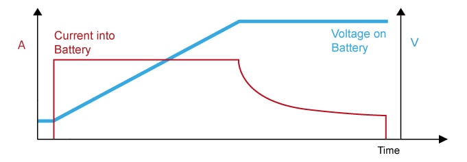
Figure 1: USB PD Eliminates multiple AC Adapters, Simplifies Wiring, and Unclutters The Desk
PPS capability allows for constant current charging (with gradual voltage increase), followed by constant voltage charging (with gradual current reduction).
USB Type-CTM Authentication: A Safety Enhancement Feature
One of a major extension introduced by USB PD 3.0 is the capability of USB Type-CTM Authentication (“C-AUTH”). While USB logos are used to identify products that have passed USB-IF (USB Implementers Forum) compliance tests, it is in fact not possible to guarantee correct USB PD operation by appearance alone. The new authentication capability helps ensure safe inter-device operation, and will be explained in some detail in our next session.
USB Type-CTM cable connections also support a new Configuration Channel (CC1 and CC2 pins), enabling devices to communicate in managing their USB PD connections other than USB data communications (see Fig. 2). Where previous USB implementations used power lines to send such information, the use of a CC makes communication much more reliable, thereby adding new support for time-critical operations. The newest USB PD specification supports IEC-63002-compliant communication between sources and devices, serving as an international specification. Because governments and certain institutions can require compliance for the devices they procure, USB PD compliance is a significant selling point.
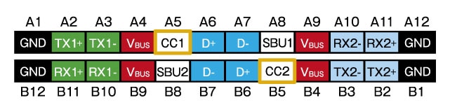
Figure 2: USB Type-CTM Pin Configuration. The two CC pins are used for USB PD communication.
USB PD 3.0 uses communication effectively to implement a variety of new capabilities. In our next session, we will look at how USB PD standards are designed with respect to assuring safety.
Module List
- USB Power Delivery (1) Enhanced Convenience in USB Charging
- USB Power Delivery (2) The Technology - Convenience and Safety
- USB Power Delivery (3) USB PD Safety Implementation USB Type-CTM Authentication (C-AUTH) of Legitimate Devices
- USB Power Delivery (4) Renesas Solutions for USB PD
- USB Power Delivery (5) Faster Development with Renesas Solutions