In the third installment of the "Let's Make a Game Using a Microcontroller!" series, we will create a slot machine game using the RL78/G23 Fast Prototyping Board (FPB).
If you haven't yet prepared your development environment, please refer to the Start Developing with the RL78 - Essential for Microcomputer Beginners - Part 1 blog for guidance.
Specifications
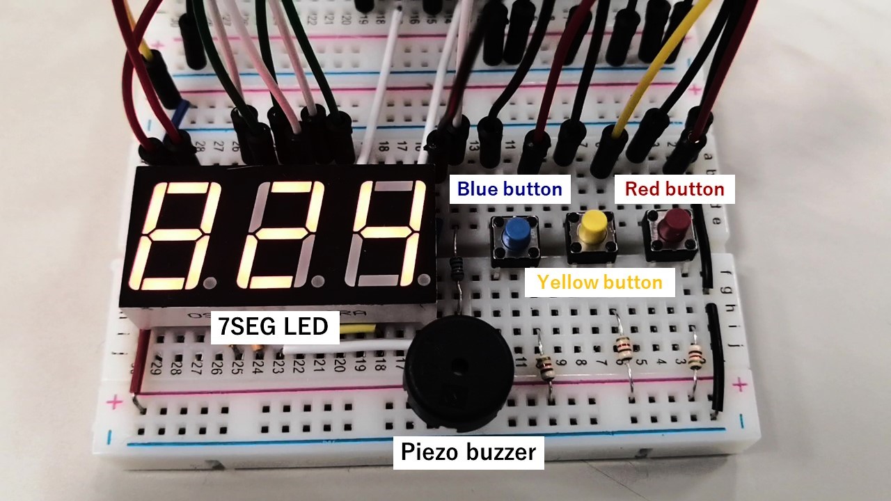
The "Slot Machine" is a game in which the numbers are aligned by pressing the switches corresponding to each digit of the 7-segment (7SEG) LEDs at the right time. The piezo buzzer mounted on the breadboard will beep when this game is successful. Below, we have posted images of the system in action.
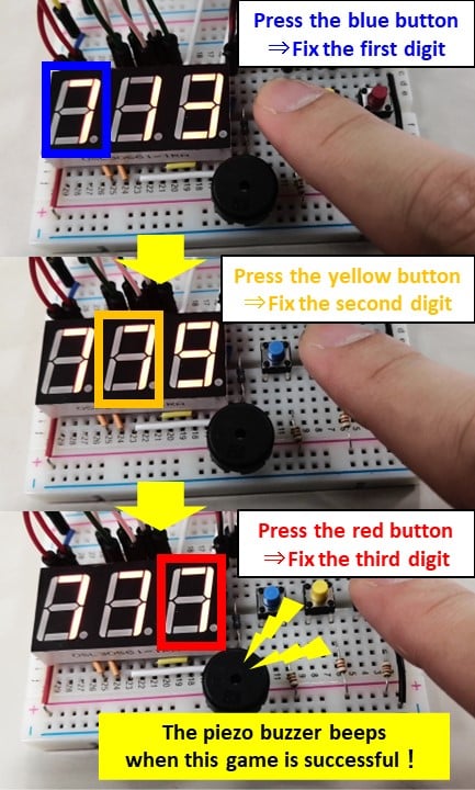
Each number is displayed on the 7-segment LED while being changed at fixed time intervals. (Figure 1)
The piezo buzzer mounted on the breadboard will beep when the player aligns the numbers by pressing the switches corresponding to each digit of the 7SEG LEDs at the right time. (Figure 2)
Hardware Design
Let me introduce the components used in the hardware design.
- RL78/G23 FPB
- Micro USB Type-B cable
- Breadboard
- Jumper wires
- Pin socket (FHU-1x42SG)
- 3-digit 7SEG LED (OSL30561-IRA)
- Tactile switch × 3
- Piezo buzzer (PKM13EPYH4000-A0)
- Source-type transistor array (M54564P)
- Sink-type transistor array (TBD62084APG)
- Resistors (470Ω × 8、10kΩ × 3、1kΩ × 1)
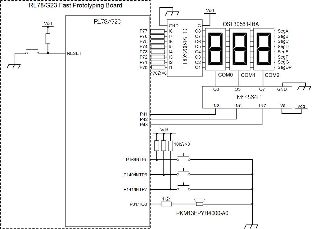
We will wire the circuit on the breadboard according to the circuit diagram shown in Figure 3.
7SEG LED Display
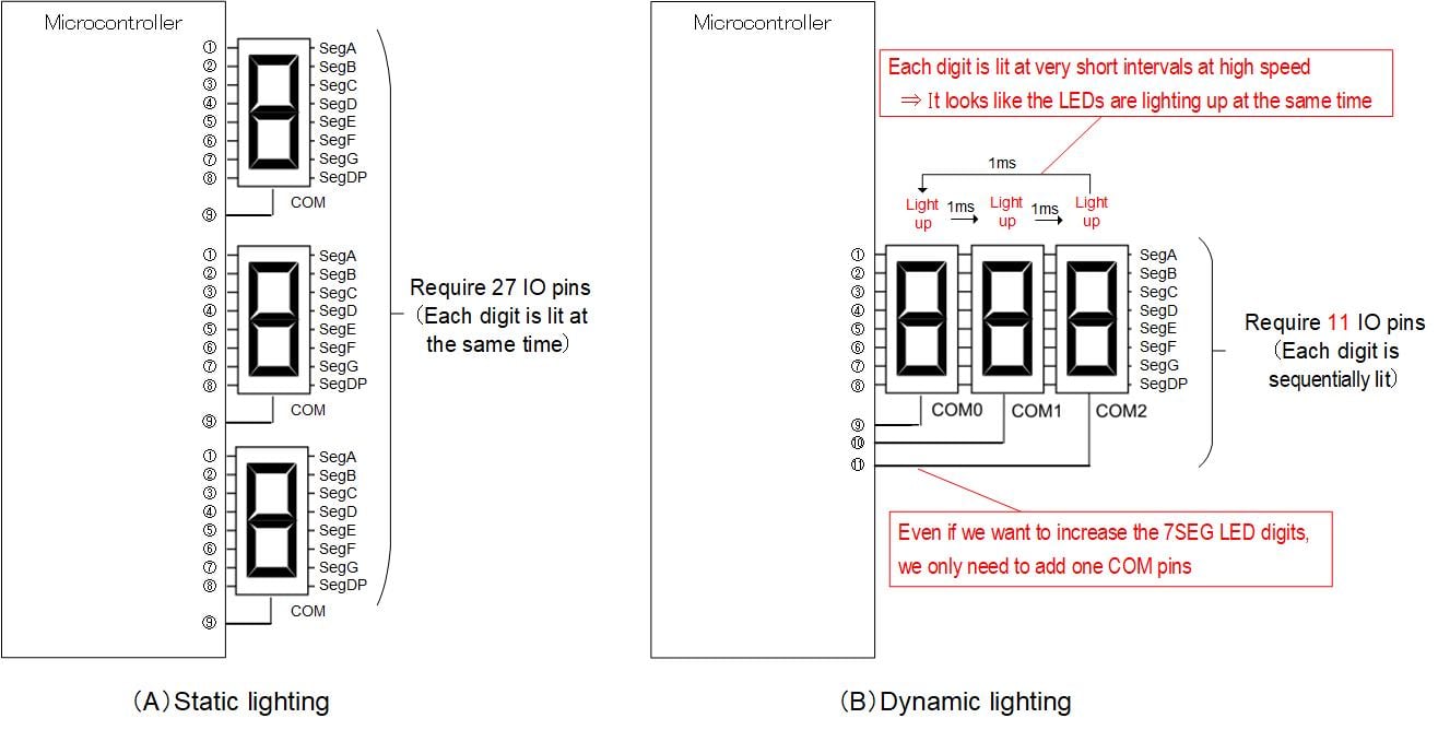
In this slot machine’s design, the 7SEG LED is set for dynamic lighting. Dynamic lighting is a method in which multiple displays are lit at very short intervals at high speed, as shown in Figure 4 (B). The program includes operations that sequentially switch and light up multiple displays, but to the human eye, the switching is so fast that it looks like the LEDs are lighting up at the same time. The advantage of this method is that it requires fewer IO pins on the microcontroller. For a 3-digit 7SEG LED display, we require 27 IO pins when the LEDs are set for static lighting, whereas only 11 IO pins when the LEDs are set for dynamic lighting. Additionally, even if we want to increase the 7SEG LED digits, we only need to add one COM pin, so the dynamic lighting is very convenient for microcontrollers that have a limited number of usable IO pins.
Software Design
I created the program using the development tool called CS+. If you haven’t installed the development tools yet, please install them following the blog post below.
Integrated Development Environment Blog: Start Developing with the RL78 - Essential for Microcomputer Beginners - Part 1
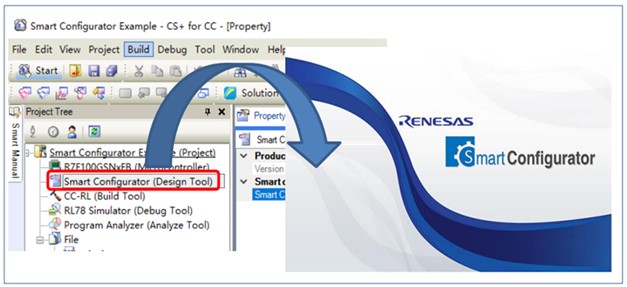
Open CS+ and click on the area highlighted in the red box in the image below (Figure 5) to launch the code generation tool (Smart Configurator). By using Smart Configurator, you can easily generate initialization functions for various peripheral functions. Be sure to take advantage of this tool.
For instructions on how to use Smart Configurator, please refer to the RL78 Smart Configurator User Guide: CS+ Edition.
Download the Slot Machine Game’s Program
Let’s run the program and play the slot machine game.
In previous blogs, we have introduced making other games using the RL78 Fast Prototyping Board. Be sure to check out the blog posts below.
Let's Make a Game Using a Microcontroller - Part 1
Let's Make a Game Using a Microcontroller - Part 2