Overview
Description
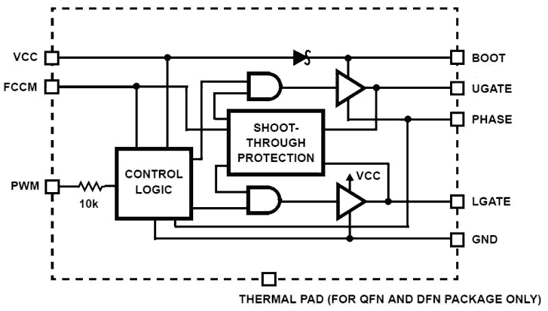
The ISL6208 and ISL6208B are high frequency, dual MOSFET drivers, optimized to drive two N-Channel power MOSFETs in a synchronous-rectified buck converter topology. They are especially suited for mobile computing applications that require high efficiency and excellent thermal performance. These drivers, combined with an Intersil multiphase Buck PWM controller, form a complete single-stage core-voltage regulator solution for advanced mobile microprocessors. ISL6208 and ISL6208B have the same function but different packages. The descriptions in this datasheet are based on ISL6208 and also apply to ISL6208B. The ISL6208 features 4A typical sinking current for the lower gate driver. This current is capable of holding the lower MOSFET gate off during the rising edge of the Phase node. This prevents shoot-through power loss caused by the high dv/dt of phase voltages. The operating voltage matches the 30V breakdown voltage of the MOSFETs commonly used in mobile computer power supplies. The ISL6208 also features a three-state PWM input that, working together with Intersil’s multiphase PWM controllers, will prevent negative voltage output during CPU shutdown. This feature eliminates a protective Schottky diode usually seen in a microprocessor power systems. MOSFET gates can be efficiently switched up to 2MHz using the ISL6208. Each driver is capable of driving a 3000pF load with propagation delays of 8ns and transition times under 10ns. Bootstrapping is implemented with an internal Schottky diode. This reduces system cost and complexity, while allowing the use of higher performance MOSFETs. Adaptive shoot-through protection is integrated to prevent both MOSFETs from conducting simultaneously. A diode emulation feature is integrated in the ISL6208 to enhance converter efficiency at light load conditions. This feature also allows for monotonic start-up into pre-biased outputs. When diode emulation is enabled, the driver will allow discontinuous conduction mode by detecting when the inductor current reaches zero and subsequently turning off the low side MOSFET gate.
Features
- Dual MOSFET drives for synchronous rectified bridge
- Adaptive shoot-through protection
- 0.5Ω On-resistance and 4A sink current capability
- Supports high switching frequency up to 2MHz
- Fast output rise and fall time
- Low propagation delay
- Three-state PWM input for power stage shutdown
- Internal bootstrap Schottky diode
- Low bias supply current (5V, 80µA)
- Diode emulation for enhanced light load efficiency and pre-biased start-up applications
- VCC POR (Power-On-Reset) feature integrated
- Low three-state shutdown holdoff time (typical 160ns)
- Pin-to-pin compatible with ISL6207
- QFN and DFN package:
- Compliant to JEDEC PUB95 MO-220 QFN - Quad flat no leads - package outline DFN - Dual flat no leads - package outline
- Near chip scale package footprint, which improves PCB efficiency and has a thinner profile
- Pb-free (RoHS Compliant)
Comparison
Applications
Applications
- Core voltage supplies for Intel® and AMD® mobile
- microprocessors
- High frequency low profile DC/DC converters
- High current low output voltage DC/DC converters
- High input voltage DC/DC converters
Design & Development
Models
ECAD Models
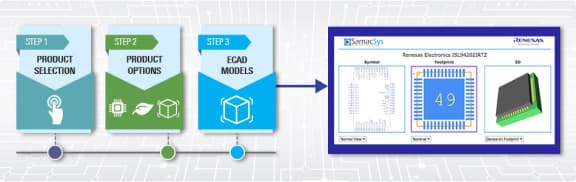
Schematic symbols, PCB footprints, and 3D CAD models from SamacSys can be found by clicking on products in the Product Options table. If a symbol or model isn't available, it can be requested directly from the website.
ISL6208BCRZ-T Active Samples Available |
DFN | Reel | 3 | 1.406 | Get Samples, |
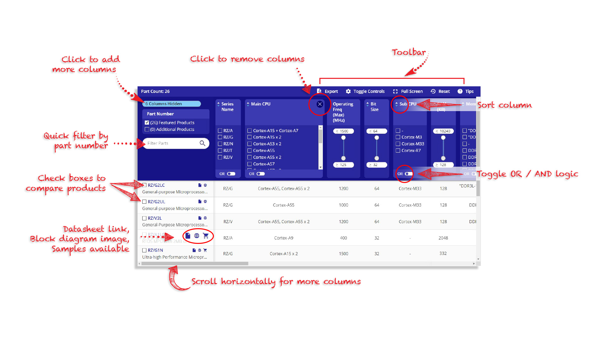
Tips for Using This Parametric Table:
- Hide Filters button in header: Collapse or expands filters
- Column sort buttons in header: Sort Column alphabetically / numerically descending or ascending
- Reset button in header: Reset all filters to the page default
- Full Screen button in header: Expand the table to full screen view (user must close out of full screen before they can interact with rest of page)
- Export button in header: Export the filtered results of the table to an Excel document
- Filter parts search bar in header: Type to filter table results by part number
- Hide column button in column headers: Select to hide columns in table
- AND / OR toggle switches in header: Toggles the logic of this particular filter to be “AND” or “OR” logic for filtering results
- Multiselect checkboxes at beginning of each row in table: Select these checkboxes to compare products against each other
- Document icon next to product name in row: View the featured document for this product
- Chip icon next to the right of the document icon in row: View the block diagram for this product
- Cart icon to the right of the chip icon: Indicates that samples are available for this product