Overview

Description

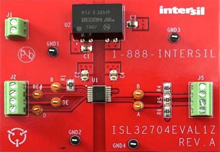
The ISL32704EVAL1Z board enables the evaluation of the ISL32704E isolated, half-duplex RS-485 transceiver in a typical bus node application, used in isolated industrial networks.

The ISL32704E is a galvanically isolated, differential bus transceiver designed for bidirectional data transmission and meeting the RS-485 and RS-422 standards for balanced communication. Each of the bus terminals, A and B, is protected against ±15kV ESD strikes without latch-up.

The device uses giant magnetoresistance (GMR) as isolation technology. A unique ceramic/polymer composite barrier provides excellent isolation and virtually unlimited barrier life.

Features

  • Tiny isolated RS-485 transceiver
  • Drive capability of up to 32 x 1UL-transceivers
  • Isolated 3.3V to 5V DC/DC converter with regulated output
  • Small total device footprint of 183mm2

Applications

Applications

  • Factory automation
  • Security networks
  • Building environmental control systems
  • Industrial/Process control networks
  • Level translators (i.e., RS-232 to RS-485)

Documentation

Document title Document type Type Date Date
PDF 513 KB Manual - Development Tools
PDF 833 KB Datasheet
2 items

Design & Development

Software & Tools

Software Downloads

Software title Software type Type Date Date
ZIP 375 KB PCB Design Files
1 item
ISL32704E Isolated RS-485 Transceiver Webinar

ISL32704E is Intersil's first, and also the world's smallest, integrated isolated RS-485 transceiver. This product webinar provides an overview of applications requiring isolated data transmission, explains galvanic isolation as well as highlights the key features and operation of the ISL32704E.

Transcript

ISL32704E - Isolated RS-485 Transceiver

Today’s session focuses on Intersil's first, and also the world's smallest, integrated isolated RS-485 transceiver: ISL32704E.

This product webinar:

  • Gives a short overview on applications requiring isolated data transmission
  • Explains galvanic isolation and its purpose
  • Discusses principle operation, inner structure and the features of the ISL32704E.

Interface Products from Intersil

Intersil was an original innovator during the early evolution of serial interface standards, including the introduction of the charge pump eliminating the negative supply voltage requirement. Our extensive portfolio gives our customers all of the choices they need to meet their serial communication needs.

Applications That Use Isolation

Isolation in general is used in many markets, ranging from medical, industrial and consumer electronics, to telecom, computer and office equipment.

RS-485 related isolators mainly find use in the industrial networks of factory and building automation and industrial robotics, as shown on the next slide.

Industrial Applications That Typically Use Isolated RS-485

Industrial networks connect programmable logic controllers (PLCs) to instruments, motor drives, data acquisition (DACQ) and digital I/O modules. The communication across the network commonly uses RS-485 as a physical layer.

At the equipment/bus interface, galvanic isolation is implemented to keep the communication bus free from common-mode noise, which is of particular importance in the electrical noisy environment of motors and generators.

A second, emerging field of applications is industrial robotics. Here, the communication between a controller and the actual robot happens via high-speed RS-485.

Technical Highlights

Next, I’ll cover some technical highlights.

Defining Galvanic Isolation

Galvanic Isolation

  • Is a means of preventing current from flowing between two communicating points while allowing the transmission of energy or information between these points.
  • Is used to eliminate ground loops while withstanding large ground potential differences (GPDs).

The information transfer within the isolator can occur via light, electric fields, or magnetic fields.

Preventing Ground Loops

The network nodes of a communication network draw their supply from different locations in the electrical installation system and use their local grounds as reference potential.

However, remotely located power sources can experience large ground potential differences (GPDs) due to non-standardized earthing techniques. GPDs are the main contributor to common-mode noise in a data link.

The left diagram shows that by simply connecting the bus node circuits to their local grounds, a ground loop is created. Here, large GPDs can cause large common-mode noise on the bus exceeding the input common-mode voltage range of a transceiver. This can cause data errors and even lead to device damage.

The right diagram shows that by inserting an isolator into the signal path, the ground loop is broken, and the common-mode voltage removed from the bus.

Thus, the use of galvanic isolators in a data link not only prevents the design of unintentional ground loops, but also ensures reliable transceiver operation in the presence of high GPDs (that can range up to the isolator's breakdown voltage).

Proper Isolation of Bus Nodes

High-speed interfaces, such as Ethernet, use transformers to isolate the differential data bus, which limits the transmission bandwidth to high-speed signals only.

However, interfaces such as RS-232, RS-422 and RS-485 operate at data rates from as low as a few kilobits per second (kbps) up to some tens of megabits per second (Mbps). Here, the most economical solution is the use of single-ended, CMOS/TTL logic isolators, implemented between the transceiver logic I/O and the adjacent UART or controller.

Of course, complete bus node isolation also requires the isolation of the local power supplies from the supplies of the bus-connected circuits using isolated DC/DC converters.

The above schematic shows both isolated grounds (GND1ISO and GND2ISO) are floating, having no relation whatsoever to the local Earth-grounds GND1 and GND2.

With the impedance of each isolation barrier being about 1014Ω, the entire common-mode voltage, previously established across the receiver inputs, is now distributed across both isolation barriers.

Smallest, Yet Most Robust RS-485 Isolator in the Market

While it is possible to design an isolated bus node using separate transceiver and isolator components, the ISL32704 combines both functions within a single package.

Optimized layout and design techniques make it possible to manufacture the device in an unprecedented, small, 4mm x 5mm QSOP package, while maintaining a whopping 600V of working voltage at a barrier lifetime of 44,000 years.

These offer a 75% smaller footprint and 50% higher working voltage than competing devices. Furthermore, the device is UL recognized and VDE certified.

Some short explanations to often encountered isolation terms:

  • Working voltage (in VRMS) is the voltage that can be applied across the isolator (between GND1 and GND2) for the entire lifetime of the device.
  • The much higher isolation -or transient overvoltage (in VRMS) is the voltage that can be applied across the isolator (between GND1 and GND2) for a minimum of 60 seconds. Here, UL and VDE specify different test methods and values.
  • The common-mode transient immunity or CMTI (in kV/µs) defines how fast a 1kV transient, applied to GND2, can ramp-up without being detected at GND1.
  • The creepage distance is the shortest path between two conductive parts measured along the surface of the insulation. The shortest distance path is found around the end of the package body.
  • Clearance is the shortest path between two conductive input to output leads measured through air (line of sight).

ISL32704E Overview

The small package of the ISL32704EIAZ not only provides tremendous cost and space savings, but also a steep increase in reliability. In comparison to other isolation technologies, GMR has the lowest failure-in-time number (FIT = 0.2), followed by capacitive and transformer isolators (FIT = 2), and optocouplers (FIT = 200).

This makes GMR the most reliable isolation technology in the industry.

The bus-sided control features of the ISL32704EIAZ are unique. In quite a few proprietary applications though, they did help by adding specific control and monitoring features to a bus node design.

Power supply range and current consumption impact the device's ease-of-use and its required board space. The ISL32704 has the lowest power consumption with up to 80% less supply current than its competitors. It can therefore operate at maximum speed within a tiny QSOP package without overheating.

While its minimum VDD1 supply of 3.0V allows for a direct interface to low-voltage controllers, its bus supply at VDD2 remains at 5V ±10% to drive large bus voltages that ensure high noise immunity.

GMR-Isolator Functional Principle

The ISL32704 utilizes a GMR isolator whose operating principle is shown in the left diagram. Here, a buffered input signal drives a primary coil, which creates a magnetic field that changes the resistance of the GMR resistors 1 to 4.

GMR1 to GMR4 form a Wheatstone bridge in order to create a bridge output voltage that only reacts to magnetic field changes from the primary coil.

Large external magnetic fields, however, are treated as common-mode fields. Since they affect all four GMRs equally, the bridge output is zero. Thus, external fields are suppressed by the bridge configuration.

The right diagram depicts the function of a single GMR resistor. This resistor consists of ferromagnetic alloy layers, B1 and B2, sandwiched around an ultra-thin, nonmagnetic, conducting middle layer, A, typically copper.

The GMR structure is designed so that, in the absence of a magnetic field, the magnetic moments in B1 and B2 face opposite directions, thus causing heavy electron scattering across layer A, which increases its resistance for current I drastically. When a magnetic field H is applied, the magnetic moments in B1 and B2 are aligned and electron scattering is reduced. This lowers the resistance of layer A and increases current flow.

Internal Structure of a GMR Isolator

The crosscut above shows the internal structure of a GMR isolator.

The current (I) flowing through the planar coil windings generates a magnetic field (H) that penetrates a proprietary polymer dielectric barrier and modifies the resistance of the magnetic sensors (GMR resistors) in bridge configuration.

The bridge output is conditioned and made available via output buffers located within the silicon substrate.

Above the planar coil windings is a passivation layer that allows for the application of a magnetic shield. This shield has two functions:

  1. Shielding the isolator structure against external magnetic fields,
  2. Strengthening the internal field and focusing it onto the GMR bridge.

Emissions: Advantages of GMR vs. Transformer Isolation

A major advantage of GMR isolation over other isolation technologies is its low radiated emission and low EMI susceptibility.

Unlike capacitive and magnetic isolators that utilize RF carriers or pulse-width modulation (PWM) to transfer DC and low-frequency signals across the barrier, GMR isolators do not require fancy encoding schemes. Neither do they include current hungry power transfer coils or transformers, as their signal transfer is virtually energy-less. The absence of the above factors not only results in a significantly lower current consumption but also causes the radiated emission spectrum to be virtually undetectable. Furthermore, because GMR isolators have no pulse train of RF carriers to interfere with, they also have very low EMI susceptibility.

Typical Isolated RS-485 Application

In a typical isolated RS-485 bus, each transceiver requires two power supplies, one for the non-isolated control side and one for the isolated bus side. On the control side, the ISL32704 allows for operation down to VDD1 = 3V, thus enabling the direct connection to 3V microcontrollers. The bus side however, requires a 5V supply to allow for the communication of strong bus signals over long distance.

This application assumes a bus length of less than 100m and thus uses only one failsafe biasing network for improved noise margin during bus idling. For longer bus lengths, failsafe biasing at both cable ends might be necessary.

Because of the use of isolated transceivers, the GND2 terminals of both transceivers are floating and any common-mode voltage is removed from the bus.

The entire common-mode voltage, mainly due to the large GPD between bus nodes, now drops across both isolation barriers. This means that any GPD between the GND1 terminals of both transceivers can be as high as the working voltage of the isolation barrier. For the ISL32704, this voltage can be as high as 600V.

ISL32704E Collateral

To ease the evaluation of the ISL32704EIAZ, a simple evaluation board is available. Supply and control signals are applied on the left side of the board, while the bus signals are taken from the right side of the board. An isolated 3.3V-to-5V DC/DC converter provides the power supply across the isolation barrier.

Engineers new to isolation are referred to application notes AN1971 and AN1972, which explain the operating principle of GMR and its implementation into signal isolators.

Engineers concerned with safety requirements for electrical systems will find important information in application note AN1973, which explains why GMR isolators, certified to VDE V 0884-10, can be used in equipment requiring compliance with the latest edition of IEC 61010-1, Edition 3.

Conclusion

GMR is not just another isolation technology but rather the isolation technology for high-speed and ultra-high-speed data transmission systems. Its virtual energy-less information transfer combined with its tiny form factor ensures barrier propagation times in the sub-nano second range. The nanosecond prop-delays specified in the datasheet are mainly contributions of the I/O buffer and the transceiver.

Thus, GMR isolators do not replace opto-isolators, mainly found in DC to 1Mbps applications, but provide complementary isolation in the high and ultra-high frequency realms.

The fact that GMR isolators are the only ones immune to single-event and total ionizing dose radiation, makes this fine technology also applicable to space and military applications.