
R8C/34K Group MCU Evaluation Board with USB Mini B Receptacle and USB VBUS Control IC
Jump to Page Section:
Overview
Description
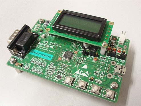
The R0K5R8C34DK2PBR evaluation board is mounted with R8C/34K Group MCU, so it is suitable for software development and functional evaluation as USB Peripheral device. This Evaluation Board can be used when you are considering about R8C/34U Group MCU, 3MK Group and 3MU Group.
Specifications
| Item | Specification |
|---|---|
| MCU |
|
| USB |
|
| Debug Function |
|
| User I/F |
|
| MCU port test pin |
|
| Operating Voltage and Supply Source |
|
| Accessory |
|
| External Dimensions |
|
*1:When the main power supply voltage is 3.3V, supply additional power (5V) to LCD, USB Host Vbus.
Notice
This product does not bundle with the power supply and the development tools. Prepare the following items before using this evaluation board.
- Power Supply 5V and 3V
- R8C Family C/C++ Compiler Package
- E8a emulator
Development support
- Please contact a Renesas sales office if you need the USB sample program.
- R8C/34K Group USB Peripheral Evaluation Board R0K5R8C34DK2PBR Hardware Instruction Manual (PDF | English, 日本語)
If you require inquiry or the purchase for product please contact your Renesas sales engineer or Renesas distributor website.

Features
- This Evaluation Board has USB mini B receptacle and USB VBUS control IC, so it is available for USB Peripheral device.
- Mounted the connector for the E8a emulator manufactured by Renesas Electronics Corp.
- This board has LCD module, LEDs, user switches as user I/F, so it is suitable for debug and functional evaluation.
- MCU ports are extracted to the board surface as test pins, this board enables the connection of external devices.
- The sample programs for USB function and each module of MCU are provided, you can immediately begin software development and functional evaluation.
- Attached the circuit diagram and the parts list, it is useful as a reference of circuit design and debug.
Applications
Documentation
Log in required to subscribe
|
|
|
|
|---|---|---|
| Type | Title | Date |
| Application Note | PDF 1.31 MB 日本語 | |
| Application Note | PDF 1.07 MB 日本語 | |
| Application Note | PDF 808 KB 日本語 | |
| Application Note | PDF 1.30 MB 日本語 | |
| Application Note | PDF 1.36 MB 日本語 | |
| Application Note | PDF 2.08 MB 日本語 | |
| Application Note | PDF 1.50 MB 日本語 | |
| Application Note | PDF 570 KB 日本語 | |
8 items
|
||