
Bidirectional Buck-Boost Voltage Regulator Evaluation Board
跳转至页面部分:
概览
简介
The ISL95338EVAL1Z evaluation board is used to evaluate the ISL95338 bidirectional buck-boost voltage regulator, which provides bidirectional buck-boost voltage regulation and protection features. Renesas' advanced R3™ Technology is used to provide high light-load efficiency, fast transient response and seamless DCM/CCM transitions.
The ISL95338 takes input power from a wide range of DC power sources (conventional AC/DC ADPs, USB PD ports, travel ADPs, etc.) and safely converts it to a regulated voltage up to 24V. The ISL95338 also can convert a wide range DC power source connected at its output (system side) to a regulated voltage to its input (ADP side). This bidirectional buck-boost regulation feature makes its application very flexible.
The ISL95338 includes various system operation functionalities such as forward mode enable, reverse mode enable, programmable soft-start time, and adjustable VOUT, in both forward direction and reverse direction. The protection functionalities include OCP, OVP, UVP, OTP, etc.
The ISL95338 offers serial communication using SMBus/I2C that allows programming of many critical parameters to deliver a customized solution. These programming parameters include, but are not limited to: output current limit, input current limit and output voltage setting.

特性
- Bidirectional buck, boost and buck-boost operation
- Input voltage range 3.8V to 24V (no dead zone)
- Output voltage up to 20V
- Up to 1MHz switching frequency
- Programmable soft-start time
- LDO output for VDD and VDDP
- System status alert function
- Bidirectional internal discharge function
- Active switching for negative voltage transitions
- Bypass mode in both directions
- Forward mode enable, Reverse mode enable
- OCP, OVP, UVP, and OTP protections
- SMBus and auto-increment I2C compatible
应用
应用
- Tablets, ultrabooks, power banks, mobile devices, and USB-C
Processing table
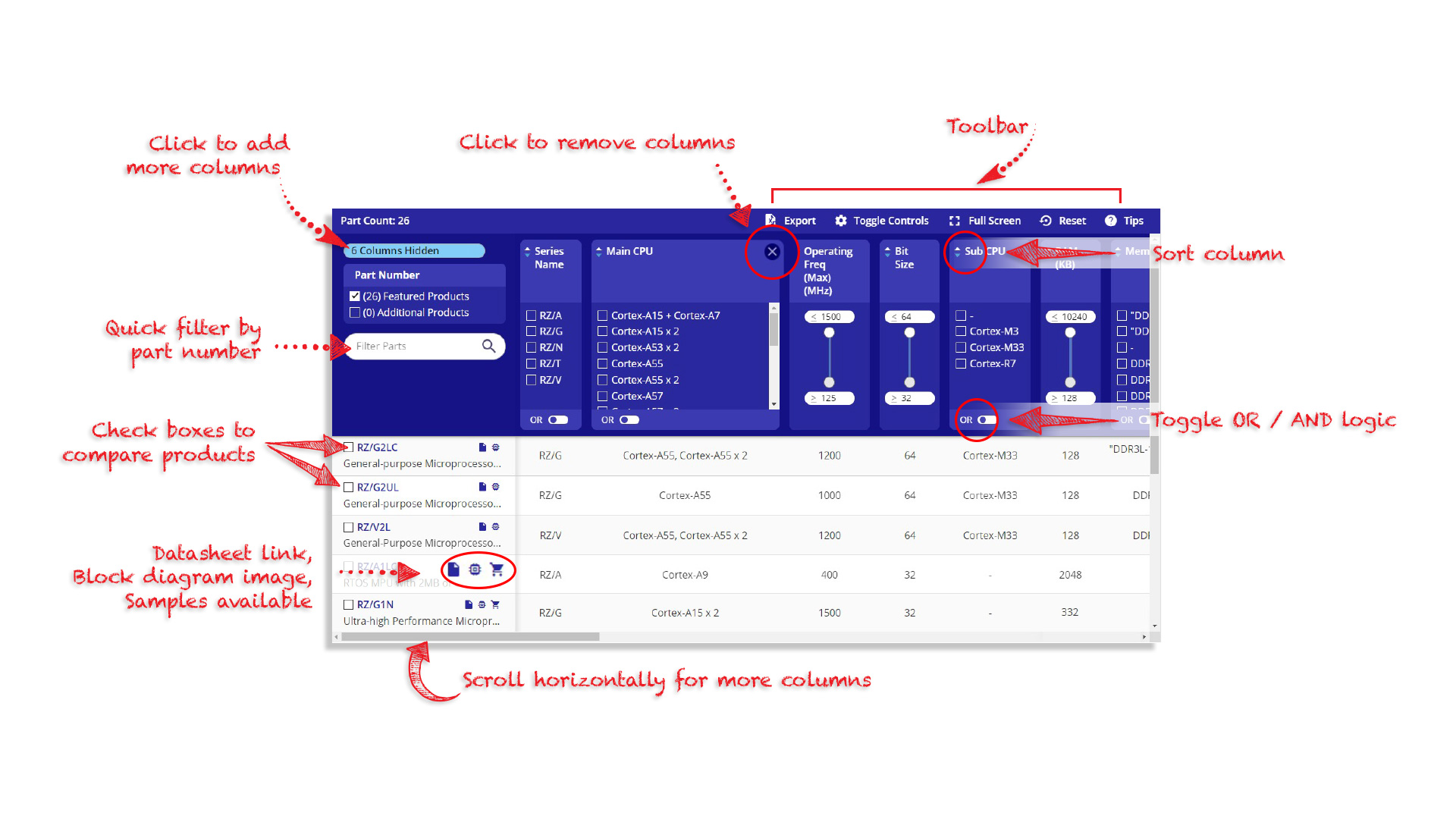
Tips for Using This Parametric Table:
- Hide Filters button in header: Collapse or expands filters
- Column sort buttons in header: Sort Column alphabetically / numerically descending or ascending
- Reset button in header: Reset all filters to the page default
- Full Screen button in header: Expand the table to full screen view (user must close out of full screen before they can interact with rest of page)
- Export button in header: Export the filtered results of the table to an Excel document
- Filter parts search bar in header: Type to filter table results by part number
- Hide column button in column headers: Select to hide columns in table
- AND / OR toggle switches in header: Toggles the logic of this particular filter to be “AND” or “OR” logic for filtering results
- Multiselect checkboxes at beginning of each row in table: Select these checkboxes to compare products against each other
- Document icon next to product name in row: View the featured document for this product
- Chip icon next to the right of the document icon in row: View the block diagram for this product
- Cart icon to the right of the chip icon: Indicates that samples are available for this product
视频和培训
Evaluating the ISL95338 USB-C Buck-Boost Regulator
Learn how to set up the ISL95338 evaluation board and connect the EVB to the GUI interface. See a demonstration of the GUI interface, forward mode, reverse mode, and phase voltages.
Transcript
Hi, my name is Phil Brinkley. I'm with Intersil, a Renesas company and today I want to demonstrate how to make use of the ISL95338 evaluation board.
First thing you do after you receive the board is to go to the landing page for the ISL95338 and download the GUI software that goes along with it as well the user's guide for the evaluation board.
The lab equipment you'll need to run the board is an adjustable DC power supply, a digital multimeter and an oscilloscope is nice to have but not essential.
Okay, once you unpack your board you want to make sure the jumpers are in the right place. This is J4 needs to be installed, J6 and seven need to be on the left side of that 3-pin header. The two switches S3 and S4 need to be to the left, being high. And switch one and switch two need to be to the right, being low.
Once you have your software installed you wanna plug in the USB. It should acknowledge with a beep that you've plugged it in and all three LEDs go on.
Forward Mode Operation
The first demo we're gonna walk through is forward mode in buck mode. So we're gonna apply power to the ADP side and measure the voltage out on the system side. Connect the multimeter up to your board to measure the output voltage on VSYS. As long as S1 is on the low side VSYS should read around 0V. Once you have your board wired up go ahead and apply 12V to the board. Should check the current on the output. It should be very low, less than a milliamp or so. You'll notice that the two LEDs go out here, that implies that we have power to the board.
So you want to click on reset USB in the upper right-hand corner once the board is powered and the USB connected. And verify that you get a green checkmark on the USB interface. Once you have a green check mark you can read the manufacturer ID and you should see 0049 hex. That indicates that the board is connected and reading the registers properly.
So for forward mode in buck mode, we wanna set the output voltage to say 5V. You'll see that it rounds up to 5.004V. You want to write that register. You can also click on write all or read all. In this case, let's read all and verify that the D08 register, or that that value, was set in the register.
Once you have written the registers to drive approximately 5V out on VSYS you can measure that and switch S1 over to high. You should see around 5V. In our case we have it commanded to be 5.004V out and are reading very close to that. So we've now demonstrated forward mode using a buck converter; 12V in, 5V out. Let's now look at reverse mode. To do so we will reverse our connections and use the GUI to enable reverse mode operation.
Reverse Mode Operation
First, disable our power supply. Turn S1 back to low and we're gonna reverse our connections. So now I'm gonna put the power coming in on VSYS and we will measure the power out on the ADP side. Okay, now that we've reversed our connections we're gonna enable power coming into the VSYS. We have 12V coming in and around 0.2mA being drawn. We're measuring the output. Currently, it's off. In the GUI I'm gonna set my reverse regulation voltage to 5V and write all the registers. I can read them to make sure that they did take and they did. And then I can enable switch two which will now turn on the output. We can see that the output measured now 5V. So we've demonstrated forward mode as well as reverse mode.
Buck to Buck-Boost to Boost Mode
Now that we've demonstrated both forward and reverse mode the other thing you can do is add an oscilloscope in. We can look at the phase voltages and watch how they change as our input voltage changes to move it from buck mode to buck-boost mode and to boost mode. So this is a look at the phase voltages. We currently have 12V coming in and 5V going out. So we're in buck mode. As I ramp down the power supply from 12V down to 7, 6, 5 now I can see it's moved into buck-boost mode and pure boost mode if I go down to 4V. As I go back up 4, to 5, to 6, you can see that we're now back into buck mode. So that's 12V in and 5V out.
Well, thanks for watching and have a great day.
Video List