
Wideband, Low-Power, Ultra-High Dynamic Range Differential Amplifier Evaluation Board
跳转至页面部分:
概览
简介
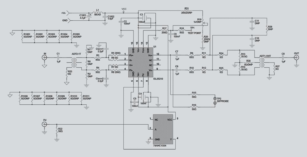
The ISL55210IRTZ-EVALZ evaluation board is used to evaluate the ISL55210 TQFN wideband, low-power, ultra-high dynamic range differential amplifier. The ISL55210 wideband differential I/O amplifier is intended principally as the last stage interface to high-performance 12- to 16-bit analog-to-digital converters (ADCs).
The primary test purpose for this board is to implement different interstage differential passive filters intended for the ADC interface along with the ADC input impedances. The board is delivered with only the output resistors loaded to give a 200Ω differential load. This is done using the two 85Ω resistors as R9 and R10, then the four 0Ω elements (R10, R12, R24, and R25) and finally the two shunt elements R13 and R14 set to 35.5Ω. The 50Ω measurement load on the output side of the 1:1 transformer reflecting in parallel with the two 35Ω resistors takes the nominal AC shunt impedance to 71Ω||50Ω = 29.3Ω. This adds to the two 85Ω series output elements to give a total load across the amplifier outputs of 170Ω + 29.3Ω = 199.3Ω.
特性
- Gain bandwidth product: 4.0GHz
- Input voltage noise: 0.85nV/√(Hz)
- Differential slew rate: 5,600V/µs
- 2VP-P, 2-tone IM3 (200Ω) 100MHz: -109dBc
- Supply voltage range: 3.0V to 4.2V
- Quiescent power (3.3V supply): 115mW
应用
应用
- Low power, high dynamic range ADC interfaces
- Differential mixer output amplifiers
- SAW filter pre/post drivers
- Differential Comms-DAC output drivers
设计和开发
软件与工具
Processing table
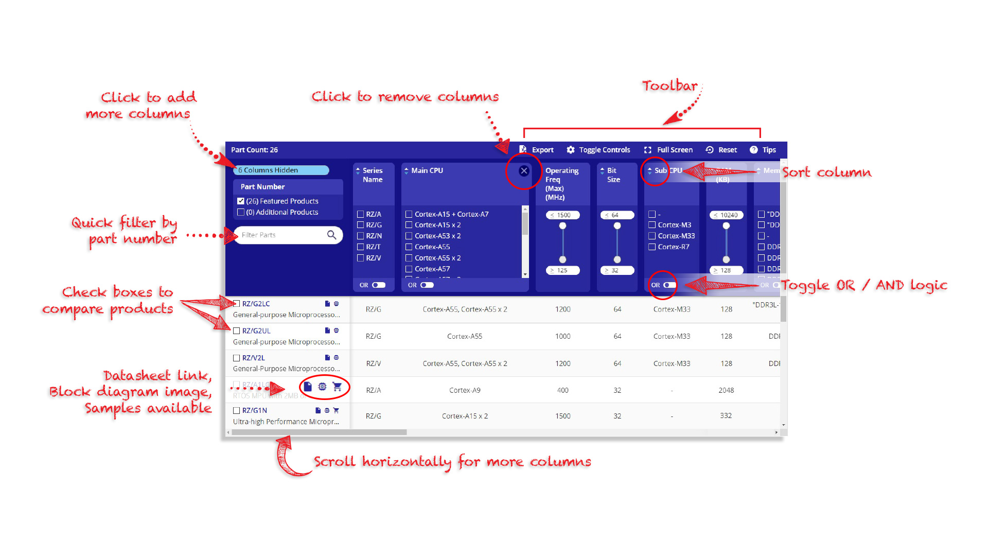
Tips for Using This Parametric Table:
- Hide Filters button in header: Collapse or expands filters
- Column sort buttons in header: Sort Column alphabetically / numerically descending or ascending
- Reset button in header: Reset all filters to the page default
- Full Screen button in header: Expand the table to full screen view (user must close out of full screen before they can interact with rest of page)
- Export button in header: Export the filtered results of the table to an Excel document
- Filter parts search bar in header: Type to filter table results by part number
- Hide column button in column headers: Select to hide columns in table
- AND / OR toggle switches in header: Toggles the logic of this particular filter to be “AND” or “OR” logic for filtering results
- Multiselect checkboxes at beginning of each row in table: Select these checkboxes to compare products against each other
- Document icon next to product name in row: View the featured document for this product
- Chip icon next to the right of the document icon in row: View the block diagram for this product
- Cart icon to the right of the chip icon: Indicates that samples are available for this product
视频和培训
ISL55210 Active Balun Evaluation Platform - Part 1
This video demonstrates some wideband single ended input to differential output options using the ISL55210 Active Balun Evaluation Platform.
Transcript
Today we're going to be discussing a new circuit technique that we've developed as part of our ISL55210. That's a very wide band, 4GHz fully differential amplifier that includes features internally that are unique to that device in the industry.
So we'll start today by looking at the legacy approaches of going from single differential, first starting with a fully differential amplifier, which has been an emerging component of the industry. It's been extremely useful for signal path processing and ADC driving. So here we see, a typical circuit that you would find in lots of suppliers' datasheets that are supplying high performance, fully differential amplifiers or FDAs, where we're trying to provide an input match to a source impedance, and gain from that matching input impedance, to a differential output swing.
Typically, what you'll see, is you'll see a circuit with a resister to ground. I call that RT for termination resister. We don't have to have a blocking cap for DC coupled for all these applications, but for simplicity here, we'll use a blocking cap, since we're comparing this to a balun approach which is necessarily AC coupled.
So we'll see resister to ground which is part of our input termination resistance and we'll typically see a resister going to the summing junction, then two equal feedback resisters will comprise the circuit. What we're trying to do with these elements is we're trying to get a 50ohm input match here, and then balance the divider equations going back to each side. So, you'll notice if you look at the impedance past the cut off frequency as a blocking capacitor, if you notice the impedance looking back each way, we'll see that it's matched. That's necessary for the differential balance.
But if you look at this circuit for just a moment, you wonder what's going on with this? We're trying to get a 50ohm input match, and that's clearly not the case looking at these two resisters. What's going on is with a fully differential amplifier as a single ended input signal moves up and down, the common mode voltage on the inputs have to move, to satisfy the common mode loop which is trying to hold the average voltage constant.
Internal to a part like the ISL55210, which would be our feature part today, we have a common mode reference voltage that defaults to 1.2V. This circuit incidentally is coming from our free online simulator that you can download and run any of the circuits I'm showing you today in a simulation package, available free from Renesas.
The ISL55210 has a model in that package that reflects all the features we're trying to describe today.
So, it is possible to hit a designed target. This is the solution for the resister to ground. All of these active termination kind of circuits, end up with a quadratic solution. Once you get this value having selected a feedback resister that's appropriate for the device you're using, a target gain and a source impedance that you're trying to match, this will give you the solution for the termination resister to ground. From that, you can get the other two resisters from these simple equations. If we can get rid of this resister, and just have the match going into the inverting summing junction, we'll find that the noise goes way down on this circuit which will always be the case if you don't throw a signal away into a terminating element to ground.
So let's go next just to some other ways of doing the single differential using a FDA.
Video List