
Time of Flight (ToF) Distance Measurement Evaluation Kit - Sand Tiger
跳转至页面部分:
概览
简介
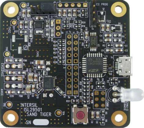
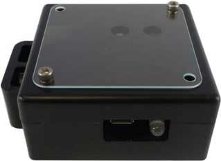
The ISL29501-ST-EV1Z is a distance measurement reference design. It combines the ISL29501 Time of Flight (ToF) based signal processing chip with an OSRAM SFH 4550 IR emitting LED and OSRAM SFH 213FA photodiode. The circuit board is enclosed in an opaque plastic chassis designed to optically isolate components. Included is a USB flash drive containing the evaluation software for a PC and related technical documents.
The ISL29501-ST-EV1Z board also allows quick evaluation of the ISL29501 performance for a 5m sensing system.
特性
- Self contained measurement system
- Enables proximity detection and distance measurement
- Emitter DAC with programmable current up to 255mA
- Operates in continuous or single shot mode
- On-chip active ambient light rejection
- Regulated power 2.7V to 3.3V USB or external supply
- I2C interface supporting 1.8V and 3.3V bus
应用
应用
- Mobile consumer applications
- Industrial proximity sensing
- Power management
- Home automation
Processing table
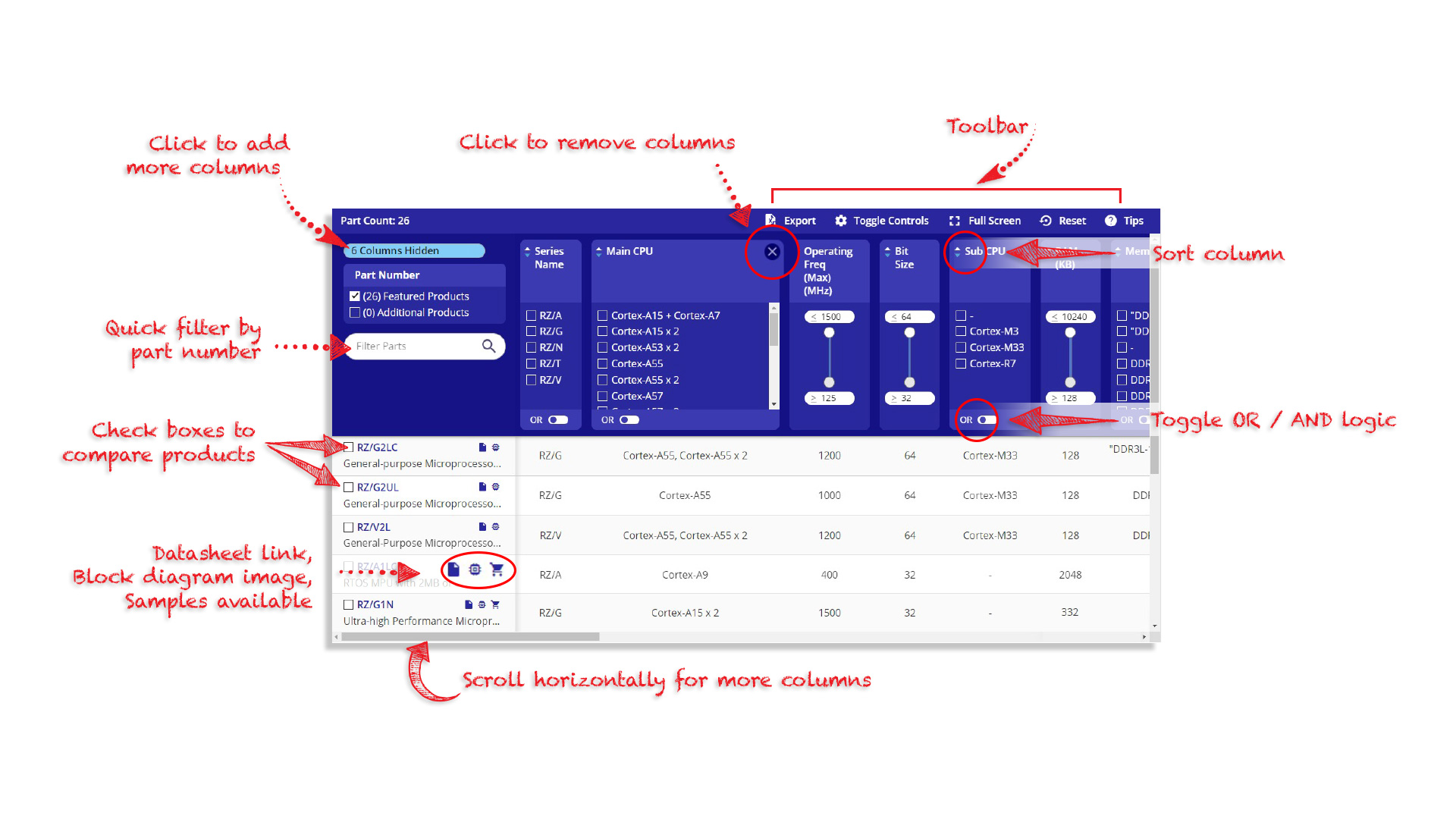
Tips for Using This Parametric Table:
- Hide Filters button in header: Collapse or expands filters
- Column sort buttons in header: Sort Column alphabetically / numerically descending or ascending
- Reset button in header: Reset all filters to the page default
- Full Screen button in header: Expand the table to full screen view (user must close out of full screen before they can interact with rest of page)
- Export button in header: Export the filtered results of the table to an Excel document
- Filter parts search bar in header: Type to filter table results by part number
- Hide column button in column headers: Select to hide columns in table
- AND / OR toggle switches in header: Toggles the logic of this particular filter to be “AND” or “OR” logic for filtering results
- Multiselect checkboxes at beginning of each row in table: Select these checkboxes to compare products against each other
- Document icon next to product name in row: View the featured document for this product
- Chip icon next to the right of the document icon in row: View the block diagram for this product
- Cart icon to the right of the chip icon: Indicates that samples are available for this product
视频和培训
Using the ISL29501 Reference Board
Learn how to use the ISL29501-ST-EV1Z Sand Tiger Reference Design Kit to measure the distance and detect objects.
Transcript
Hello, my name is Celine Baron. I am applications interim manager for optical products. I am going to show you now how to operate our Time of Flight ISL29501 Sand Tiger Reference Board. This is the evaluation kit you just received. In this evaluation kit you will find multiple components. The first one is a USB key that contains our software GUI to operate the board as well as the relevant technical documentation to perform your own evaluation.
You will also find, of course, our ISL29501 Sand Tiger board. If you open it, which is not necessary for the evaluation, you will be able to identify the optical components which are part of the system, a photo diode and an LED. The ISL29501 chip is located on the other side of the PCB. In the kit, you will find also a USB cable, that will allow you to connect the board to a PC for power and communication purposes. Last, you will find a black target. This black target will be used if you want to perform a manual calibration of the board.
I am going to show you now, how to quickly operate the board. First of all, install the GUI on your computer from the USB key and connect the board. Then you can open the tof.exe file that will start the GUI. And first you will read and accept our license. You will scroll down and click on 'Accept'. Then the board is ready to operate. You can confirm that the board is powered up, looking at the red LED that we have here. Let me demonstrate now how the part works.
First, I will load a profile clicking on 'File', 'Load Profile', and I select one of the two profiles available, then I just have to click on 'Start' and the board is completely operational. A first example of application is to point the board towards the target.
You can see two signals on the GUI, the magnitude and the distance in meters. Here I am measuring the distance between the board and the target. If now I introduce an object, my hand for instance, between the board and the target, you will see that the distance measure drops, because now I'm measuring the distance between the board and my hand. If my hand goes closer and closer to the board, the measure of distance obviously decreases.
More information on the GUI functionality is provided in the software manual. Thank you for watching.
Video List