Household Gas Alarm Reference Design
The Household Gas Alarm is a system that warns people with a flashing LED and buzzing alarm as soon as a change in carbon monoxide concentration is detected due to gas...

RL78/G10 microcontrollers realize the industry's lowest level of consumption current (CPU: 46 μA/MHz, standby (STOP): 560 nA). With an on-chip oscillator, A/D converter, comparator, and more, and a 10/16-pin package lineup, they support more compact system size. These low pin count microcontrollers are perfect for small consumer electronics.
| Software title
|
Software type
|
Company
|
|---|---|---|
| Sound Playback/Compression System [M3S-S2-Tiny] for RL78 Family Sound playback system for RL78 Family
|
Sound / Voice | Renesas |
| AP4, Applilet Peripheral I/O driver generator compatible with third-party compilers and GNU compiler (for RZ, V850, RX, RL78, and 78K)
|
Code Generator | Renesas |
| Applilet EZ PL for RL78 Programming software that can easily create microcontroller application software like assembling a puzzle, without using programming languages
|
Code Generator | Renesas |
| Code Generator Plug-in Automatic driver generation tool for internal peripheral I/O modules through GUI settings [Standard features for Renesas IDE "e² studio" and CS+] [Support MCU/MPU: RL78, V850, 78K, RX]
|
Code Generator | Renesas |
| C Compiler Package for RL78 Family [CC-RL] C Compiler Package for RL78 Family [IDE: CS+, e² studio]
|
Compiler/Assembler | Renesas |
| E2 emulator [RTE0T00020KCE00000R] On-chip debugging emulator. Also available as a flash memory programmer. [Support MCU/MPU: RA, RE, RH850, R-Car D1, RL78, RX, RISC-V MCU]
|
Emulator | Renesas |
| E2 emulator Lite [RTE0T0002LKCE00000R] On-chip debugging emulator. Also available as a flash memory programmer. [Support MCU/MPU: RA, RE, RL78, RX, RISC-V MCU]
|
Emulator | Renesas |
| PG-FP6 Flash memory programmer [Programming software: Dedicated GUI-based software, the "FP6 Terminal"] [Support MCU/MPU and devices: RA, RE, RX, RL78, RH850, RISC-V MCU, Renesas Synergy, Power Management, Renesas USB Power Delivery Family, ICs for Motor Driver/Actuator Driver, SuperH RISC engine, V850, 78K, R8C]
|
Programmer (Unit/SW) | Renesas |
| Renesas Flash Programmer (Programming GUI) Flash memory programming software [Support MCU/MPU and devices: RA, RE, RX, RL78, RH850, RISC-V MCU Renesas Synergy, DA1459x, DA1469x, DA1470x, Power Management, Renesas USB Power Delivery Family, ICs for Motor Driver/Actuator Driver, V850, 78K0R, 78K0]
|
Programmer (Unit/SW) | Renesas |
| Simulator for e² studio of RL78 Family Simulator for RL78 Family [Support IDE: e² studio] (Note: This product is included in the Renesas IDE "e² studio" and is not available separately.)
|
Simulator | Renesas |
| RL78 Web Simulator Right online tools to support initial evaluation of the low power consumption RL78 Family. Lineup: MCU Simulator Online and Current Consumption Calculator. Free of charge.
|
Simulator | Renesas |
| QE for Current Consumption: A Dedicated Tool for Current Measurement Development assistance tool helps to shorten the times taken in operations for the tuning of currents drawn. [Standard item in the "e² studio" and CS+ (CS+ for CC only) IDEs] [Support MCU/MPU: RX, RL78]
|
Solution Toolkit | Renesas |
| CS+ Renesas integrated development environment (IDE) [Support MCU/MPU: RH850, V850, RX, RL78, 78K0R, 78K0]
(Note: CS+ is not generally promoted to U.S. and European customers.)
(Note: To use Smart Configurator on CS+ for RL78/G23 and RX family MCUs, install the Smart Configurator for each MCU family separately downloading from ”Design & Support” > ”Development Tools” > ”Smart Configurator”)
|
IDE and Coding Tool | Renesas |
| e² studio - information for RL78 Family Eclipse-based Renesas integrated development environment (IDE).
|
IDE and Coding Tool | Renesas |
| IAR Embedded Workbench for Renesas RL78 IAR Embedded Workbench provides extensive support for RL78 devices. IAR Embedded Workbench is a complete set of development tools with leading optimization technology for creating powerful automotive applications.
|
IDE and Coding Tool | IAR Systems |
| Renesas IAR Embedded Workbench Device-Support-Packages Renesas IAR Embedded Workbench Device-Support-Packages include all device-specific files to be used with the Embedded Workbench IDE.
|
IDE and Coding Tool | Renesas |
|
16 items
|
||
The Household Gas Alarm is a system that warns people with a flashing LED and buzzing alarm as soon as a change in carbon monoxide concentration is detected due to gas...
This Infrared Human Sensor reference design detects human presence/absence using an infrared sensor, and turns on/off a high brightness LED automatically. It can be...
As a CPU board usable in connection with the on-chip debugging emulator E2, E2 Lite, E1(discontinued product), this product achieves simple and easy evaluation of the...
As a CPU board usable in connection with the on-chip debugging emulator E1 or MINICUBE2, this product achieves simple and easy evaluation of the target MCU.
The Smart Power Strip is a popular household appliance, which is widely used in intelligent linkage control and power saving of connected devices.
This Smart Power...
This is a solution that could be installed on windows and door entrances, etc. When a vibration caused by an outside force is detected, an alarm will sound to scare off...
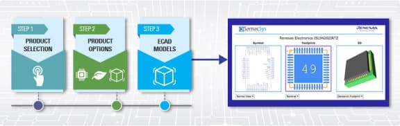
Schematic symbols, PCB footprints, and 3D CAD models from SamacSys can be found by clicking on products in the Product Options table. If a symbol or model isn't available, it can be requested directly from the website.
PLP |
Program Memory (KB) |
RAM (KB) |
Lead Count (#) |
Temp. Range |
Bit Size |
CPU |
Data Flash (KB) |
Supply Voltage (V) |
Operating Freq (Max) (MHz) |
RTC |
LVD |
DMA |
I/O Ports |
Timer |
ADC |
DAC |
CAN (ch) |
Ethernet |
USB |
Human Machine Interface |
Moisture Sensitivity Level (MSL) |
Price (USD) | 1ku |
Buy / Sample |
|
|---|---|---|---|---|---|---|---|---|---|---|---|---|---|---|---|---|---|---|---|---|---|---|---|---|
| Part Number | ||||||||||||||||||||||||
| N/A | 1 | 0.125 | 10 | -40 to 85°C | 8 | RL78 | 0 | 2 - 5.5 | 20 | Yes | No | No | 8 | 16-bit x 2-ch | 10-bit x 4-ch | 0 | No | 3 | 0.3939 | Get Samples, | ||||
| 2033 Dec | 1 | 0.125 | 10 | -40 to 85°C | 8 | RL78 | 0 | 2 - 5.5 | 20 | Yes | No | No | 8 | 16-bit x 2-ch | 10-bit x 4-ch | 0 | No | 3 | ||||||
| N/A | 1 | 0.125 | 16 | -40 to 85°C | 8 | RL78 | 0 | 2 - 5.5 | 20 | Yes | No | No | 14 | 12-bit x 1-ch, 16-bit x 4-ch | 10-bit x 7-ch | 0 | No | 3 | 0.4696 | Get Samples, | ||||
| 2033 Dec | 1 | 0.125 | 16 | -40 to 85°C | 8 | RL78 | 0 | 2 - 5.5 | 20 | Yes | No | No | 14 | 12-bit x 1-ch, 16-bit x 4-ch | 10-bit x 7-ch | 0 | No | 3 | ||||||
| N/A | 2 | 0.25 | 16 | -40 to 85°C | 8 | RL78 | 0 | 2 - 5.5 | 20 | Yes | No | No | 14 | 12-bit x 1-ch, 16-bit x 4-ch | 10-bit x 7-ch | 0 | No | 3 | 0.5151 | Get Samples, | ||||
| 2033 Dec | 2 | 0.25 | 16 | -40 to 85°C | 8 | RL78 | 0 | 2 - 5.5 | 20 | Yes | No | No | 14 | 12-bit x 1-ch, 16-bit x 4-ch | 10-bit x 7-ch | 0 | No | 3 | 0.5151 | |||||
| N/A | 4 | 0.5 | 16 | -40 to 85°C | 8 | RL78 | 0 | 2 - 5.5 | 20 | Yes | No | No | 14 | 12-bit x 1-ch, 16-bit x 4-ch | 10-bit x 7-ch | 0 | No | 3 | 0.5605 | Get Samples, | ||||
| 2033 Dec | 4 | 0.5 | 16 | -40 to 85°C | 8 | RL78 | 0 | 2 - 5.5 | 20 | Yes | No | No | 14 | 12-bit x 1-ch, 16-bit x 4-ch | 10-bit x 7-ch | 0 | No | 3 | 0.5605 | |||||
| N/A | 4 | 0.5 | 10 | -40 to 85°C | 8 | RL78 | 0 | 2 - 5.5 | 20 | Yes | No | No | 8 | 16-bit x 2-ch | 10-bit x 4-ch | 0 | No | 3 | 0.4393 | Get Samples, | ||||
| 2033 Dec | 4 | 0.5 | 10 | -40 to 85°C | 8 | RL78 | 0 | 2 - 5.5 | 20 | Yes | No | No | 8 | 16-bit x 2-ch | 10-bit x 4-ch | 0 | No | 3 | ||||||
| N/A | 2 | 0.25 | 10 | -40 to 85°C | 8 | RL78 | 0 | 2 - 5.5 | 20 | Yes | No | No | 8 | 16-bit x 2-ch | 10-bit x 4-ch | 0 | No | 3 | 0.3939 | Get Samples, | ||||
| 2036 Mar | 2 | 0.25 | 10 | -40 to 85°C | 8 | RL78 | 0 | 2 - 5.5 | 20 | Yes | No | No | 8 | 16-bit x 2-ch | 10-bit x 4-ch | 0 | No | 3 | ||||||
| N/A | 4 | 0.5 | 10 | -40 to 85°C | 8 | RL78 | 0 | 2 - 5.5 | 20 | Yes | No | No | 8 | 16-bit x 2-ch | 10-bit x 4-ch | 0 | No | 3 | 0.3939 | Get Samples, | ||||
| 2033 Dec | 4 | 0.5 | 10 | -40 to 85°C | 8 | RL78 | 0 | 2 - 5.5 | 20 | Yes | No | No | 8 | 16-bit x 2-ch | 10-bit x 4-ch | 0 | No | 3 | 0.3939 | |||||
| N/A | 4 | 0.5 | 16 | -40 to 85°C | 8 | RL78 | 0 | 2 - 5.5 | 20 | Yes | No | No | 14 | 12-bit x 1-ch, 16-bit x 4-ch | 10-bit x 7-ch | 0 | No | 3 | 0.5151 | Get Samples, | ||||
| 2033 Dec | 4 | 0.5 | 16 | -40 to 85°C | 8 | RL78 | 0 | 2 - 5.5 | 20 | Yes | No | No | 14 | 12-bit x 1-ch, 16-bit x 4-ch | 10-bit x 7-ch | 0 | No | 3 | 0.5151 | |||||
| N/A | 2 | 0.25 | 16 | -40 to 85°C | 8 | RL78 | 0 | 2 - 5.5 | 20 | Yes | No | No | 14 | 12-bit x 1-ch, 16-bit x 4-ch | 10-bit x 7-ch | 0 | No | 3 | 0.4696 | Get Samples, | ||||
| 2033 Dec | 2 | 0.25 | 16 | -40 to 85°C | 8 | RL78 | 0 | 2 - 5.5 | 20 | Yes | No | No | 14 | 12-bit x 1-ch, 16-bit x 4-ch | 10-bit x 7-ch | 0 | No | 3 | ||||||
| N/A | 1 | 0.125 | 16 | -40 to 85°C | 8 | RL78 | 0 | 2 - 5.5 | 20 | Yes | No | No | 14 | 12-bit x 1-ch, 16-bit x 4-ch | 10-bit x 7-ch | 0 | No | 3 | 0.4393 | Get Samples, | ||||
| 2033 Dec | 1 | 0.125 | 16 | -40 to 85°C | 8 | RL78 | 0 | 2 - 5.5 | 20 | Yes | No | No | 14 | 12-bit x 1-ch, 16-bit x 4-ch | 10-bit x 7-ch | 0 | No | 3 | ||||||
| 2033 Dec | 1 | 0.125 | 10 | -40 to 85°C | 8 | RL78 | 0 | 2 - 5.5 | 20 | Yes | No | No | 8 | 16-bit x 2-ch | 10-bit x 4-ch | 0 | No | 3 | 0.3939 | |||||
| 2036 Mar | 2 | 0.25 | 10 | -40 to 85°C | 8 | RL78 | 0 | 2 - 5.5 | 20 | Yes | No | No | 8 | 16-bit x 2-ch | 10-bit x 4-ch | 0 | No | 3 | 0.3939 | |||||
| 2033 Dec | 4 | 0.5 | 10 | -40 to 85°C | 8 | RL78 | 0 | 2 - 5.5 | 20 | Yes | No | No | 8 | 16-bit x 2-ch | 10-bit x 4-ch | 0 | No | 3 | 0.3939 | |||||
| 2033 Dec | 4 | 0.5 | 10 | -40 to 85°C | 8 | RL78 | 0 | 2 - 5.5 | 20 | Yes | No | No | 8 | 16-bit x 2-ch | 10-bit x 4-ch | 0 | No | 3 | 0.4393 | |||||
| 2033 Dec | 1 | 0.125 | 16 | -40 to 85°C | 8 | RL78 | 0 | 2 - 5.5 | 20 | Yes | No | No | 14 | 12-bit x 1-ch, 16-bit x 4-ch | 10-bit x 7-ch | 0 | No | 3 | 0.4393 | |||||
| 2033 Dec | 1 | 0.125 | 16 | -40 to 85°C | 8 | RL78 | 0 | 2 - 5.5 | 20 | Yes | No | No | 14 | 12-bit x 1-ch, 16-bit x 4-ch | 10-bit x 7-ch | 0 | No | 3 | ||||||
| 2033 Dec | 2 | 0.25 | 16 | -40 to 85°C | 8 | RL78 | 0 | 2 - 5.5 | 20 | Yes | No | No | 14 | 12-bit x 1-ch, 16-bit x 4-ch | 10-bit x 7-ch | 0 | No | 3 | 0.4696 | |||||
| 2033 Dec | 2 | 0.25 | 16 | -40 to 85°C | 8 | RL78 | 0 | 2 - 5.5 | 20 | Yes | No | No | 14 | 12-bit x 1-ch, 16-bit x 4-ch | 10-bit x 7-ch | 0 | No | 3 | ||||||
| 2033 Dec | 4 | 0.5 | 16 | -40 to 85°C | 8 | RL78 | 0 | 2 - 5.5 | 20 | Yes | No | No | 14 | 12-bit x 1-ch, 16-bit x 4-ch | 10-bit x 7-ch | 0 | No | 3 | 0.5151 | |||||
| 2033 Dec | 4 | 0.5 | 16 | -40 to 85°C | 8 | RL78 | 0 | 2 - 5.5 | 20 | Yes | No | No | 14 | 12-bit x 1-ch, 16-bit x 4-ch | 10-bit x 7-ch | 0 | No | 3 |