

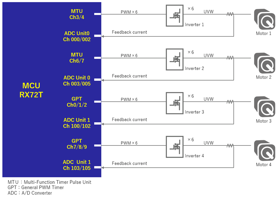
As MCUs have been improving their functionality and performance, the number of motors controlled by a single MCU is increasing from one to several, aiming for the size and cost reduction of systems. The trend is especially noticeable in washing machines and air conditioners, and most of these products now are adopting multiple-motor control. This time, I will introduce a demonstration of controlling 4 motors using the RX72T, which can control multiple motors by a single MCU.
Depending on the motor control method, the processing performance and the function resources required for MCU will vary. This demo uses the sensorless vector control method. Though sensor-less vector control could achieve high efficiency and enables BOM cost reduction, the CPU processing performance to compute motor angle estimation and vector control algorithm is more demanding. The RX72T incorporates the best-in-class CoreMark score CPU, the third generation RXv3 Core (6.01coremark/MHz), and Arithmetic Unit for Trigonometric Functions (TFU), offering high-speed calculation and vector control processing required to control up to 4 motors. In addition, the RX72T also features functions required for 4-motor control like complementary PWM timers and the ADCs.
Functions used in 4-motor control
In this demo, four motors are controlled with the following functions.
| Function | Description |
|---|---|
| MTU, GPT | To generate complementary PWM outputs for the inverter driver. 2 Timers MTU and GPT generate PWM outputs for 4 motors. |
| 12bit ADC | To detect motor currents and inverter bus voltage. The RX72T has 3 units of ADC, which can be assigned for 4 motors. |
| POE, POEG | To detect abnormality to shutdown output when an overcurrent occurs. POE is for MTU, and POEG is for GPT. |
Key points of the 4-motor control system
Timing of current detection
In this demo, the speed of four motors is controlled via separate sensorless vector control, and to do so, it is necessary to detect each motor’s currents and output appropriate PWM waveforms. To achieve multiple-motor control, the timing of current detection and that of performing control calculation are crucial. I will give a short description of these here. This demo uses two-phase currents detection method to calculate three-phase currents.
The RX72T incorporates 3 units of ADC in total, and in this demo, unit 0 is assigned to detect the currents of Motor 1 and Motor 2, and unit 1 is assigned to detect the currents of Motor 3 and Motor 4. The currents of the motors which are assigned to the same unit could not be detected simultaneously, so the detecting timing must be shifted. Also, since the current is detected using the shunt resistor during the lower arm of the inverter is ON, the active levels of the positive/negative phase of PWM signals for Motor 1 and Motor 2, as well as for Motor 3 and Motor 4, should be set inversely to prevent the signals to the lower arms of the inverters are ON at the same time. Therefore, the timing of A/D conversion is distributed to the crests and troughs of the PWM carrier cycles so that each motor current is detected consequently. And the group scan mode of the A/D converter enables a single unit to detect the currents of 2 motors.
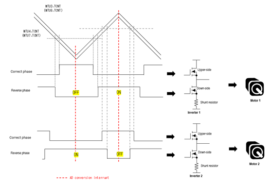
* The current of Motor 1 is detected at the crests of the PWM carrier cycle, while the current of Motor 2 is detected at the troughs.
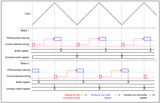
Processing time
Next, let’s look at the overall timeline of motor control including processing time. 3 critical timings needed to pay attention to here are PWM interrupt processing (vector control processing), A/D conversion for current detection, and transfer timing of the PWM setting of the buffer registers.
For Motor 1 and Motor 2, the AD conversion start is synchronized to the crests or troughs of the MTU timer. The processing time of the interruption of the PWM cycle and the transfer timing of the PWM setting of the buffer registers must be set carefully so that they are coordinated with the next AD conversion. For Motor 3 and Motor 4, the approach is the same, except for using the GPT timer.
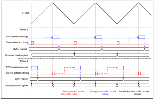
* For Motor 4, the compare register isn’t updated at the trough, so the operation is the same as Motor
If MTU and GPT are started simultaneously with the same carrier frequency, and the MTU’s and GPT’s interrupts have the same priority level, the interrupt processing is executed in order of the occurrence of interrupts. Then, the control cycle should be set so that these interrupts are processed within the control period. When using the RX72T, the processing time for each motor is about 8µs, and it doesn’t cause a problem in this demo because the current control cycle is set to 50µs.
Demonstration of 4-motor control
The board used in this demo is not for sale, however, you could check the actual operation through the video on our website. If you are interested in multiple-motor control, please refer to it and its application note as an example.
Video: Speed Control of 4Motors With A Single MCU
- APN: Sensorless Vector Control for Permanent Magnet Synchronous Motor (Implementation) (Control over Four Motors) RX72T, for "Evaluation System for BLDC Motor" Rev.1.00
- Sample Code: RX72T Sensorless Vector Control for Permanent Magnet Synchronous Motor (Implementation) (Control over Four Motors) for "Evaluation System for BLDC Motor" Rev.1.00 - Sample Code
In the end
This demo fully utilizes the features of the RX72T to implement 4-motor control, which could be used as a reference for multiple-motor control. If you are considering multiple-motor control, we highly recommend the RX72T and the sample code for reference. Other than sensorless vector control, we also provide sample code and application note on vector control for 3-motor control using encoders and RX72T. If you are interested, please refer to them as well and try multiple-motor control using the RX72T.
For vector control with an encoder over three motors, visit here.
- APN: Vector Control for Permanent Magnet Synchronous Motor with Encoder (Implementation) (Control over Three Motors) RX72T, for "Evaluation System for BLDC Motor" Rev.1.00
- Sample Code: RX72T Vector Control for Permanent Magnet Synchronous Motor with Encoder (Implementation) (Control over Three Motors) for "Evaluation System for BLDC Motor" Rev.1.00 - Sample Code