
3A Single Channel High-Efficiency DC/DC Step-Down Power Module Evaluation Board
跳转至页面部分:
概览
简介
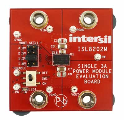
The ISL8202MEVAL1Z evaluation board is designed to demonstrate the performance of the ISL8202M 3A single channel high-efficiency DC/DC step-down power module. The board is by default set to be 1.2V output voltage with 1.5MHz switching frequency. Other output voltage values can be easily set by changing the jumper position. The switching frequency can be adjusted by changing the FS pin resistor.
The ISL8202M power module is a single-channel synchronous step-down complete power supply, capable of delivering up to 3A of continuous current. Operating from a single 2.6V to 5.5V input power rail and integrating a controller, power inductor and MOSFETs, the ISL8202M can achieve up to 95% conversion efficiency. It also provides fast transient response with excellent loop stability as well as delivers output voltage as low as 0.6V. Switching frequency is also adjustable from 680kHz to 3.5MHz with either an external resistor or SYNC clock option. Selectable PFM mode can also be enabled to boost up light-load efficiency to extend battery life. Other features include programmable soft-start, soft-stop, input undervoltage lockout, 100% duty cycle operation, over-temperature, overcurrent/short-circuit with hiccup mode, overvoltage and negative overcurrent protection. It also has a dedicated enable pin and power-good flag that allow for easy system power rails sequencing.
特性
- 2.6V to 5.5V input voltage range
- Adjustable output voltage as low as 0.6V with ±1.6%
- Accuracy over line/load/temperature
- Default 1.8MHz current mode control operations
- 680kHz to 3.5MHz resistor adjustable
- External synchronization up to 3.5MHz
- Selectable light-load efficiency mode
- 100% duty cycle LDO mode
- Programmable soft-start and soft-stop output discharge
- Dedicated enable pin and power-good flag
- UVLO, over-temperature, overcurrent, overvoltage, and negative overcurrent protections
应用
应用
- DC to DC POL power module
- µC/µP, FPGA and DSP power
- Portable equipment
- Battery operated equipment
设计和开发
软件与工具
Processing table
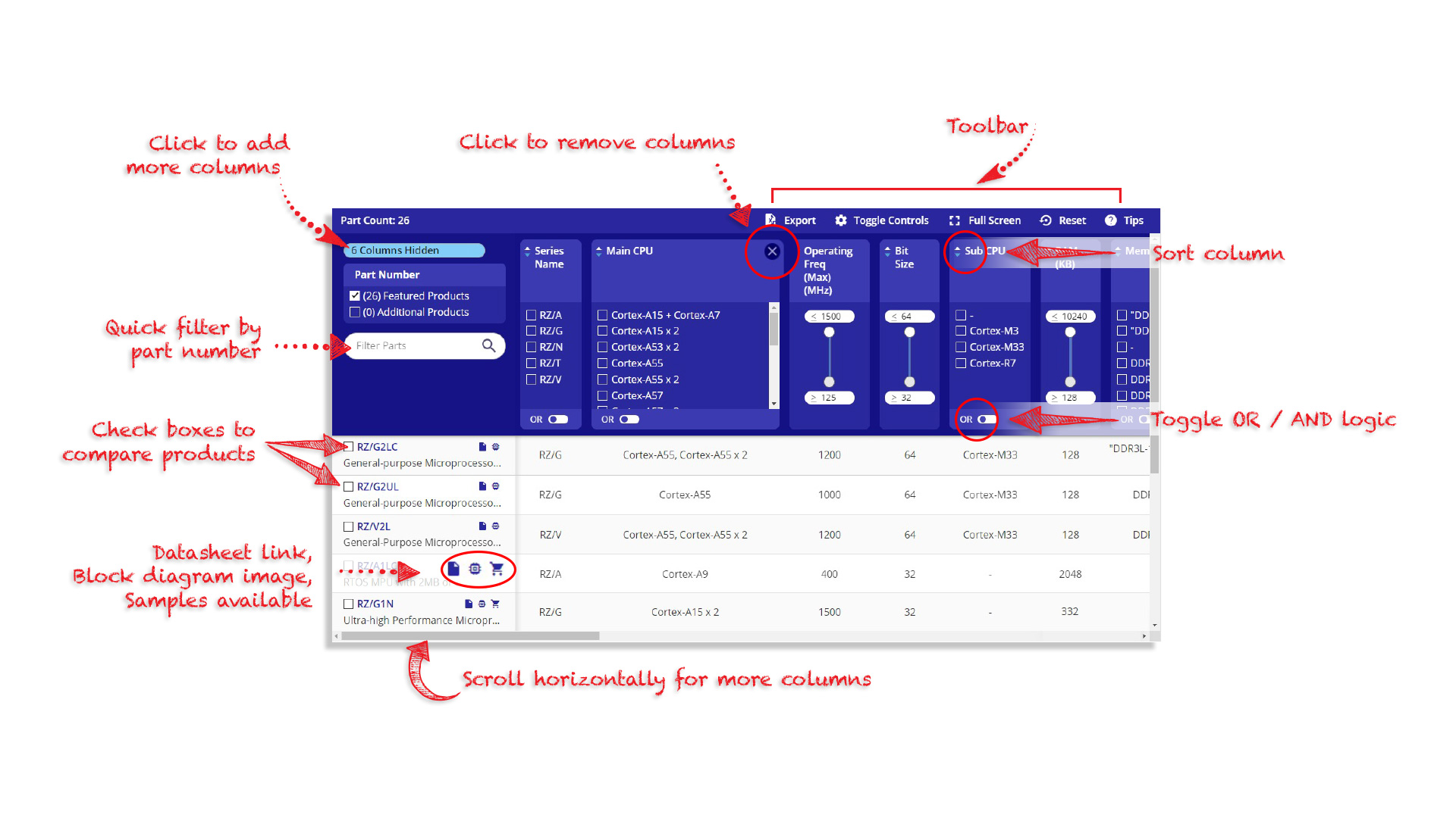
Tips for Using This Parametric Table:
- Hide Filters button in header: Collapse or expands filters
- Column sort buttons in header: Sort Column alphabetically / numerically descending or ascending
- Reset button in header: Reset all filters to the page default
- Full Screen button in header: Expand the table to full screen view (user must close out of full screen before they can interact with rest of page)
- Export button in header: Export the filtered results of the table to an Excel document
- Filter parts search bar in header: Type to filter table results by part number
- Hide column button in column headers: Select to hide columns in table
- AND / OR toggle switches in header: Toggles the logic of this particular filter to be “AND” or “OR” logic for filtering results
- Multiselect checkboxes at beginning of each row in table: Select these checkboxes to compare products against each other
- Document icon next to product name in row: View the featured document for this product
- Chip icon next to the right of the document icon in row: View the block diagram for this product
- Cart icon to the right of the chip icon: Indicates that samples are available for this product
视频和培训
ISL8202M, ISL8205M 3A/5A Step-Down Power Modules
Introducing the power dense, compact power modules ISL8202M and ISL8205M, ideal for battery-operated applications. Intersil demonstrates the selectable light-load efficiency mode and 100% duty cycle LDO mode, which enable better efficiency and lower power consumption at light-load.
Transcript
ISL8202M/05M 3A/5A Single-Channel, High Efficiency DC to DC Step-Down Power Modules
Hello and welcome to Intersil. I'm Eric Pittana, Senior Product Marketing Manager in the industrial power group. And today, I'd like to introduce to you not one but two new devices, part of Intersil's family of fully encapsulated power module: the ISL8202M and ISL8205M. When compared to a traditional implementation of the point of load, a lot of precaution has to be taken into selecting the controller, the FETS, the inductor, the drivers, in order to meet certain performance and size criteria for the point of load being designed.
The ISL8202M and ISL8205M integrate all those components in a small 4.5mm x 7.5mm package reducing the guesswork related to developing a point of load solution. Now immediately, benefits can come to mind. The first one is the compactness of the overall solution increasing to a higher power density, reachable on a PCB board. The second one is the ease of design and use. Only a few components have to be selected to make this part operate. The performance is very predictable, because now all the solution, all the power module has been characterized, and in essence, are less sensitive to component variation and aging.
Finally, with a height of 1.85mm, this power module can easily be mounted on the backside of the PCB board, freeing a valuable space for a top-sided mounted components. For this exercise and this video, we're gonna be using an ISL8205M evaluation board sitting here. We're gonna review some of the specific features and characteristic of the solution. So let's turn it on.
Here on the scope, we have three pieces of information: the input voltage, currently sitting at around 5V, the output voltage, 1.2V, and the switching node underneath. This device supports anywhere from 2.6V to 5.5V input voltage range. The output voltage range can be as low as 0.6V. The evaluation board, as a matter of fact, provides you with an easy setting that selects some of the most common output voltages in use in the electronic industry.
The output current will be set through a classical chroma load. In this case, we are actually, currently running at 5A output, the maximum output current available for the ISL8202 and ISL8205M. Some of the specific features of the part makes it very suitable for battery operated equipment, one of which being the capability of the ISL8205M to be configured to support a light load boosted efficiency mode. It is selectable because some designs prefer to stay with a constant frequency, whereas others, battery operated typically may require to use a variable frequency in order to boost the light load efficiency, meaning below anywhere, below 700mA of output current.
We see here that we are currently running at 3A of output current. I'm gonna switch down to 50mA. One thing that we're observing immediately is that our switching node operates by burst pulses. This is also known as pulse skipping or burst mode in the literature. I can go from one to the other, and we can see that the power will react immediately to a light load condition by halting essentially the switching mode, turning off the bottom FET and essentially allowing the output cap and the output to discharge fully into the load.
Another specific feature of the ISL8205M specifically targeted to the battery operation is the capability of supporting 100% duty cycle, also called LDO mode. In this case, the power module is capable of adjusting its output duty cycle in case the input voltage reaches very close to the output voltage selected. This is typical of a battery voltage, decaying overtime between charges. In this case, we've set the output voltage to 3.3V. We're still running at 5V input. I'm gonna slowly take down the input voltage to reach closer to the 3.3V desired output.
One thing that we can observe is that at a certain point, my switching node has stopped switching essentially, turning on the top FET constantly, and the difference between the input and the output voltage remains constant or about 200mV, in this case. As I keep going down, this delta is going to be maintained for as long as possible until eventually, the part input voltage collapses and the part turns off, because we've hit the undervoltage lock-up situation.
Video List