
Introductory Gadget Building: 3 of 4
In this third session, we begin the building process by connecting up the hardware. Since this is an introductory project, we won't be doing any soldering. We will build the circuits simply by pushing components into the GR-SAKURA board and a breadboard.
Getting the Parts Ready
The table below shows a list of the parts you will need. The major parts are the GR-SAKURA board (for control), the sensor (to detect the heartbeat), and the servo motor (to drive the fan). All parts are general-purpose components that can be readily purchased from numerous sources.
Because we will be using a breadboard, no soldering will be required. All we need to do is push the electronic components and jumper wire into the holes on the breadboard. So the entire assembly will be very easy.
Part List for Heartbeat Fan
Available from multiple suppliers. "Suggested Seller" column is for reference.
| Part | Part No. | Suggested Seller |
|---|---|---|
| GR-SAKURA-FULL | RS Components Element14 |
|
| Heartbeat sensor | SFE-SEN-11574 | Sparkfun (Switch Science) |
| Jumper wire (male/male) | EIC-UL1007-MM-015 | Switch Science |
| SparkFun miniature breadboard (white) | SFE-PRT-12043 | Sparkfun (Switch Science) |
| DC jack for breadboard (2.1-mm) | SSCI-DC-BB | Switch Science |
| GWS servo motor (MICRO/2BBMG/JR) | M-01725 | GWS (Akizukiki Denshi Tsusho) |
| Carbon membrane resistor (1/4-W 1-kΩ) | R-25102 | Akizuki Denshi Tsusho |
| General-purpose compact high-speed switching diode (60-V 150-mA) 1S2076A | I-03015 | Akizuki Denshi Tsusho |
| Ceramic capacitor (0.1-µF 50-V) | P-05202 | Akizuki Denshi Tsusho |
| Electrolytic capacitor (100-µF 25-V 85℃) | P-03122 | Akizuki Denshi Tsusho |
| Battery snap with 2.1-mm DC plug | P-06687 | Akizuki Denshi Tsusho |
| Battery box (1-row, four AA batteries) | P-02682 | Akizuki Denshi Tsusho |
Figure 1: Part List for Heartbeat Fan (Available from multiple suppliers. "Suggested Seller" column is for reference.)
The following items are also required: one USB cable (to connect the GR-SAKURA to your computer) and four NiMH AA batteries.
Are you concerned that you won't be able to connect the electronic components—the capacitors, resistor, and diode—correctly? No need to worry—just connect them up as indicated below. We won't worry about how they actually work right now—we'll look at that in the second half of the session.
Note also that the USB cable from your computer will provide the power to drive the GR-SAKURA, but cannot deliver sufficient power to drive the servo motor. To drive the motor, therefore, we will use four AA nickel metal hydride (NiMH) batteries. These batteries will be packed into a battery box; the box will snap onto a battery snap that ends with a DC plug; and this plug will connect to a DC jack connected to another plug on the breadboard.
The Circuit Diagram: The Key to Understanding
Figure 2 shows the circuit diagram for the heartbeat fan. The sensor sends out the detected pulse information as an analog signal (as a voltage change). This signal flows to the analog/digital converter (ADC) located within the RX63N microcontroller in the GR-SAKURA. The ADC converts the analog signal into a digital signal, which is then processed by the microcontroller in accordance with the program you will create. As the end result of this processing, the microcontroller outputs a pulse signal to the servo motor, causing it to drive the fan. (Refer to Part 1 of this series for greater detail about the system's operation.)
If you look closely at the diagram, you will see that it presents three types of information: (1) it identifies each electronic part by type; (2) it shows the rated value for each part; and (3), it shows how these parts are interconnected. So if you review the diagram carefully, you will get a clear understanding of how the overall system works.
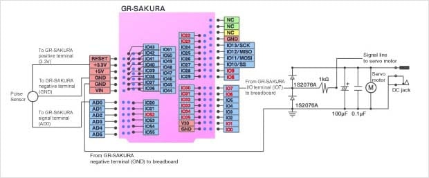
Figure 2: Circuit Diagram for Heartbeat Fan
The circuit diagram shown above only covers the GR-SAKURA I/O connections that are related to this heartbeat fan project. For a more detailed circuit diagram, download the file below:
Assembling the Hardware
Now let's prepare and install the various components. No need to feel intimidated! The work for this project is quite simple, and can be completed in about 30 minutes. So let's go.
1. Prepare the heartbeat sensor.
Take out the contents of the sensor kit. Then peel off one of the included round vinyl stickers, and adhere this sticker over the front of the sensor—over the heart image. Next, take one of the hook dots and stick it over the back of the sensor (directly over the various exposed contacts). Then attach the Velcro tape to the dot, so that it makes a ring for your finger. When using the sensor, you will want to adjust the tape so that the ball of your finger falls directly on the LED lamp. (Also, see Getting Started Guide.)
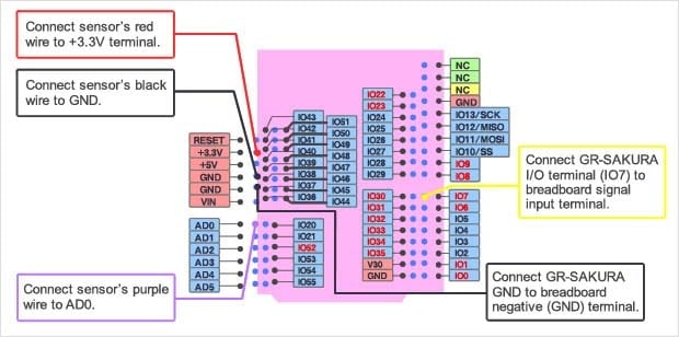
2. Connect the heartbeat sensor to the GR-SAKURA.
Connect the three wires from the sensor to the GR-SAKURA. Connect the red wire to the +3.3V terminal; the black wire to one of the GND terminals; and the purple wire to the AD0 terminal. (See Figure 3.) The GR-SAKURA will now supply power to the sensor through the red and black wires, and will input the analog sensor signal through the purple wire.
3. Connect the GR-Sakura to the breadboard.
Use two jumper wires to connect the GR-SAKURA to the breadboard, Run one of the wires from the GR-SAKURA's remaining GND terminal to a negative (GND) connector on the breadboard. Run the second wire from IO7 on the GR-SAKURA to an I/O terminal on the breadboard. The second wire will now serve as the signal wire, with the signal moving out from IO7 into the breadboard. (See Figures 3 and 4.)
4. Mount breadboard parts and make connections.
This is the only step where you need to use a tool. Because the leads on the capacitors, resistor, and diode are too long for insertion into the breadboard, you need to clip them down to appropriate size with a wire cutter or nipper. Be careful not to cut too much: if the leads are too short, they won't go in firmly, resulting in poor contact and incorrect operation. In general, try to leave a little excess length. (Note that the component bodies do not have to be flush against the breadboard; the components will work just as well even if sticking out a bit.) Look carefully at Figure 4, and then connect all of the components and jumpers accordingly.
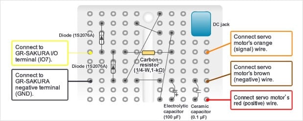
Figure 4: Board Layout and Wiring Diagram
The diode and the electrolytic capacitor both have polarity (directionality), and must be positioned in the correct orientation.
- Be sure that the arrow and black band are oriented as shown in the diagram.
- On the capacitor, the wire extending out above the gray band is the negative lead.
Note that three wires extend from the servo motor—one orange, one brown, and one red. The tips of these wires are the connectors. Insert these into the breadboard to make the connection.
Jumpers come in various colors. A rough rule for color coding is that red is the power line (positive voltage) and black is GND (negative line of power circuit). Try to use consistent color coding throughout all of your projects.
Very Important!
Checking the Sensor's Output Signal Voltage
We have already used an oscilloscope to measure the output voltage produced by the heartbeat sensor. The results are shown in Figure 5. (Note that there is no need for you to use an oscilloscope to complete this project.)

Figure 5: Output from Heart-Rate Sensor, as Measured by Oscilloscope
We supplied 5V power to the sensor when measuring with the oscilloscope. As you can see from Figure 5, the analog signal output by the sensor ranges from about 1.5V to about 5V.
Note that the sensor's maximum output voltage is approximately the same as the power voltage into the sensor. Now here's a very important fact: the A/D converter in the RX63N microcontroller (in the GR-SAKURA) can only accept a maximum input voltage of 3.3V. Since we do not wish to break the microcontroller, our design calls for us to connect the sensor's power line to the 3.3V power terminal on the GR-SAKURA. Since the sensor will not output a voltage that exceeds its own power voltage, this setup will ensure that the sensor output will not exceed 3.3V. The sensor's output line, in turn, gets connected to the GR-SAKURA's AD0 (analog input) terminal. (See "Connect the heartbeat sensor to the GR-SAKURA" above.)
Safety First! Some Electronic Precautions…
In this project, the servo motor is connected to and controlled from the microcontroller. This means that we need to a take a few precautions. First, we want to protect against noise—since noise from the motor can cause errors in the GR-SAKURA's operation. We do this by wiring in our two capacitors—one ceramic, and one electrolytic—in parallel. This will help suppress voltage fluctuations in the power line, keeping noise out of the GR-SAKURA. (See Tutorial #1, below.)
Next, we need to protect the microcontroller from damage. Note that GR-SAKURA terminal IO7 provides the PWM signal that will control the servo motor. This terminal is capable of withstanding 5V—so there will no problem with a direct connection provided that the servo motor stays within its guaranteed power rating. But there is always a risk that voltage will spike above 5V, causing a reverse voltage into the GR-SAKURA that would break the microcontroller. We will take two types of precaution to protect against this. First, we will include a resistor into the circuit, to ensure that any short circuit in the motor (inadvertent contact between the motor's positive and GND power lines) will not result in over-current. (See Tutorial #2, below.) And second, we will insert a diode, so that any over-voltage that may occur in the motor cannot propagate into the live power line. (See Tutorial #3.)
Tutorial #1: Why the Capacitors?
A capacitor is a passive component that stores and releases energy. Without the capacitor, the sudden demand for power that occurs when the motor starts up will cause the voltage to drop, generating electrical noise that can cause unstable operation and may even cause damage to the microcontroller. When the capacitor is in place, however, it will release its stored energy to meet the sudden demand, allowing the system to stabilize without significant voltage fluctuation.
Tutorial #2: Why the Resistor?
A resistor is a passive component that resists the flow of electric current. In this project, the resistor protects the microcontroller by helping to prevent excess current flow.
Tutorial #3: Why the Diode?
A diode is an active component whose purpose is to permit current flow in one direction only. In this project, the purpose of the diode is to protect the microcontroller against reverse currents and voltages that may arise at the servo motor.
Reference:
Introduction to Electronic Circuits – Part 1 Passive Elements
Introduction to Electronic Circuits – Part 2 Diodes, Transistors, and FETs

Check the breadboard arrangement and wiring one more time to make sure everything is correctly set up for our next and last session, where we will create the software and start everything up. We will then see first-hand how the sensor's output signal is detected and used to drive the fan. See you then.