
Single Digitally Controlled (XDCP™) Potentiometer
Jump to Page Section:
Overview
Description
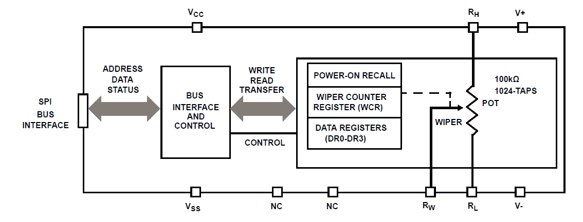
The X9110 integrates a Single Digitally Controlled Potentiometer (XDCP) on a monolithic CMOS integrated circuit. The digital controlled potentiometer is implemented using 1023 resistive elements in a series array. Between each element are tap points connected to the wiper terminal through switches. The position of the wiper on the array is controlled by the user through the SPI bus interface. The potentiometer has associated with it a volatile Wiper Counter Register (WCR) and four non-volatile Data Registers that can be directly written to and read by the user. The contents of the WCR controls the position of the wiper on the resistor array though the switches. Power-up recalls the contents of the default data register (DR0) to the WCR. The XDCP can be used as a three-terminal potentiometer or as a two terminal variable resistor in a wide variety of applications including control, parameter adjustments and signal processing.
Features
- 1024 Resistor taps – 10-bit resolution
- SPI serial interface for write, read, and transfer operations of the potentiometer
- Wiper resistance, 40Ω typical at 5V
- Four nonvolatile data registers
- Nonvolatile storage of multiple wiper positions
- Power-on recall, loads saved wiper position on power-up
- Standby current < 5μA maximum
- System VCC: 2.7V to 5.5V operation
- Analog V+/V-: -5V to +5V
- 100kΩ end-to-end resistance
- 100 year data retention
- Endurance: 100,000 data changes per bit per register
- 14 Ld TSSOP
- Dual supply version of the X9111
- Low power CMOS
- Pb-free (RoHS compliant)
Comparison
Applications
Applications
- Circuit Level Applications Vary the gain of a voltage amplifier Provide programmable dc reference voltages for comparators and detectors Control the volume in audio circuits Trim out the offset voltage error in a voltage amplifier circuit Set the output voltage of a voltage regulator Trim the resistance in Wheatstone bridge circuits Control the gain, characteristic frequency and Q-factor in filter circuits Set the scale factor and zero point in sensor signal conditioning circuits Vary the frequency and duty cycle of timer ICs Vary the dc biasing of a pin diode attenuator in RF circuits Provide a control variable (I, V, or R) in feedback circuits
- System Level Applications Adjust the contrast in LCD displays Control the power level of LED transmitters in communication systems Set and regulate the DC biasing point in an RF power amplifier in wireless systems Control the gain in audio and home entertainment systems Provide the variable DC bias for tuners in RF wireless systems Set the operating points in temperature control systems Control the operating point for sensors in industrial systems Trim offset and gain errors in artificial intelligent systems
Design & Development
Software & Tools
Models
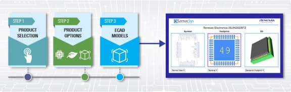
ECAD Models
Schematic symbols, PCB footprints, and 3D CAD models from SamacSys can be found by clicking on products in the Product Options table. If a symbol or model isn't available, it can be requested directly from the website.
Processing table
| TSSOP | Tube | 380 | ||
| TSSOP | Tube | 380 | ||
| TSSOP | Reel | 2500 | ||
| TSSOP | Tube | 380 | ||
| TSSOP | Tube | 380 | ||
| TSSOP | Reel | 2500 |
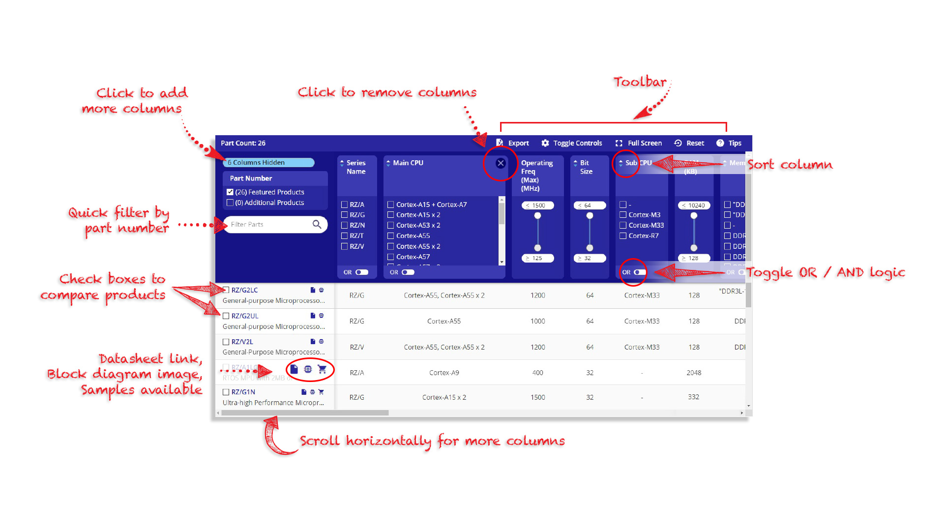
Tips for Using This Parametric Table:
- Hide Filters button in header: Collapse or expands filters
- Column sort buttons in header: Sort Column alphabetically / numerically descending or ascending
- Reset button in header: Reset all filters to the page default
- Full Screen button in header: Expand the table to full screen view (user must close out of full screen before they can interact with rest of page)
- Export button in header: Export the filtered results of the table to an Excel document
- Filter parts search bar in header: Type to filter table results by part number
- Hide column button in column headers: Select to hide columns in table
- AND / OR toggle switches in header: Toggles the logic of this particular filter to be “AND” or “OR” logic for filtering results
- Multiselect checkboxes at beginning of each row in table: Select these checkboxes to compare products against each other
- Document icon next to product name in row: View the featured document for this product
- Chip icon next to the right of the document icon in row: View the block diagram for this product
- Cart icon to the right of the chip icon: Indicates that samples are available for this product