
1-to-8 Differential to Universal Output Clock Divider/Fanout Buffer
Jump to Page Section:
Overview
Description
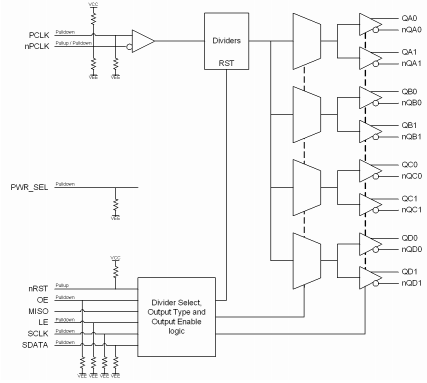
The IDT8T79S828-08I is a high performance, 1-to-8, differential input to universal output clock divider and fanout buffer. The device is designed for frequency-division and signal fanout of high-frequency clock signals in applications requiring four different output frequencies generated simultaneously. Each bank of two outputs has a selectable divider value of ÷1 thru ÷6 and ÷8. The
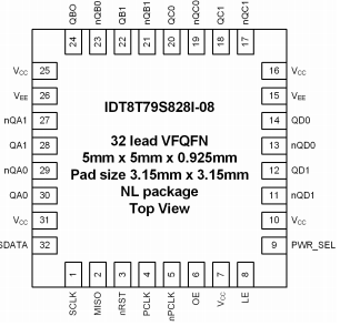
IDT8T79S828-08I is optimized for 3.3V and 2.5V supply voltages and a temperature range of -40°C to 85°C. The device is packaged in a space-saving 32 lead VFQFN package.
Features
-
Four banks of two low skew outputs
-
Selectable bank output divider values: ÷1 through ÷6 and ÷8
-
Individual outputs remain enabled while serial loading new device configurations
-
One differential PCLK, nPCLK input
-
PCLK, nPCLK input pair can accept the following differential input levels: LVPECL, LVDS or CML levels
-
Maximum input frequency: 1.5GHz
-
LVCMOS control inputs
-
QXx ÷1 edge aligned to QXx ÷n edge
-
Individual output divider control via serial interface
-
Individual output enable/disable control via serial interface
-
Individual output type control, LVDS or LVPECL, via serial interface
-
2.375V to 3.465V supply voltage operation
-
-40°C to 85°C ambient operating temperature
-
Available in lead-free (RoHS 6) package
Comparison
Applications
Design & Development
Models
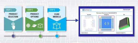
ECAD Models
Schematic symbols, PCB footprints, and 3D CAD models from SamacSys can be found by clicking on products in the Product Options table. If a symbol or model isn't available, it can be requested directly from the website.
Processing table
| VFQFPN | 32 | I | Yes | Tray | 3 | 14.01 | Get Samples, | |
| VFQFPN | 32 | I | Yes | Reel | 3 |
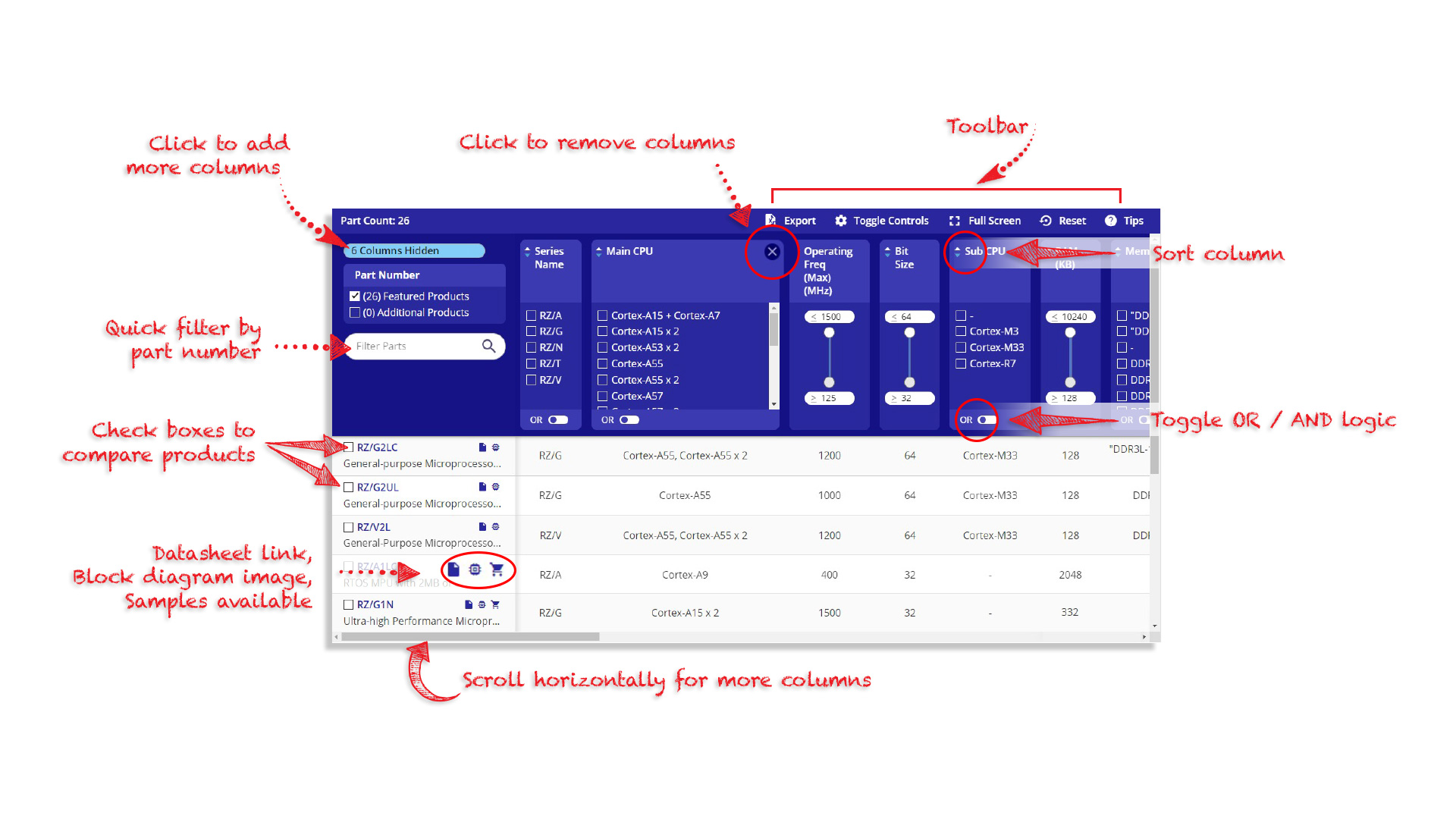
Tips for Using This Parametric Table:
- Hide Filters button in header: Collapse or expands filters
- Column sort buttons in header: Sort Column alphabetically / numerically descending or ascending
- Reset button in header: Reset all filters to the page default
- Full Screen button in header: Expand the table to full screen view (user must close out of full screen before they can interact with rest of page)
- Export button in header: Export the filtered results of the table to an Excel document
- Filter parts search bar in header: Type to filter table results by part number
- Hide column button in column headers: Select to hide columns in table
- AND / OR toggle switches in header: Toggles the logic of this particular filter to be “AND” or “OR” logic for filtering results
- Multiselect checkboxes at beginning of each row in table: Select these checkboxes to compare products against each other
- Document icon next to product name in row: View the featured document for this product
- Chip icon next to the right of the document icon in row: View the block diagram for this product
- Cart icon to the right of the chip icon: Indicates that samples are available for this product
Videos & Training
Introduction to Timing Commander™ Software Tool by IDT
Description
IDT's innovative support tool, Timing Commander™, expedites development cycles by empowering customers to program sophisticated timing devices with an intuitive and flexible Graphical User Interface. IDT's Timing Commander is a Windows™-based platform designed to serve user-friendly configuration interfaces, known as personalities, for various IDT products and product families. With a few simple clicks, the user is presented with a comprehensive, interactive block diagram offering the ability to modify desired input values, output values, and other configuration settings. The software automatically makes calculations, reports status monitors, and prepares register settings without the need to reference a datasheet. The tool also automatically loads the configuration settings over USB to an IDT evaluation board for immediate application in the circuit. Once the device has been configured and tuned for optimal system performance, the configuration file can be saved for factory-level programming prior to shipment. Presented by Steven Gutierrez, Senior Product Application Engineer at IDT. For more information, visit our Timing Commander page.
Transcript
Hi, I'm Stephen Gutierrez, and over the course of the next few minutes, I will be sharing with you some of the features of Timing Commander, the new support tool for I.D.T. timing products.
Timing commander can support a single device or a family of devices from a single file. Currently, we are viewing a family of devices from the U.F.T. product line, and for this demo, we will be using the IDT-8T49N-283 device.
Timing Commander provides complete documentation that allows users to understand the function of each setting without having to consult the data sheet. As the user hovers over an element via a specific setting or a functional block, a tool tip containing detailed information appears. Many of the I.D.T timing products are complex, highly configurable devices. Timing Commander simplifies this configuration process by making the commonly used settings available at the top level.
In this case, all the user has to enter are the input frequencies and the output frequencies. As you have just noticed, the built-in optimization algorithm has configured the device on the fly, updating the functional blocks and the diagram with each of my inputs. Aside from providing information about valid settings, Timing Commander also validates the user inputs to ensure that they remain within the data sheet's specifications.
Here I have entered an invalid setting, and Timing Commander displays an error message plus a link that will direct me to the location of that error. Once corrected, the error message goes away. For users that want to access more detailed settings, Timing Commander provides a search tool that will help them quickly locate the settings.
For example, when searching for gain, Timing Commander will highlight the functional blocks and the setting that match the search term. In addition to the diagram view, Timing Commander also provides a bit-set view and a register view. The bit-set view displays the device settings with descriptive names and detailed information. The user can click on a bit-set to view more details or also search for a term. In addition to the bit-set view, the register view will allow a user to change individual settings.
The nice feature is that changes made in the bit-set view or register view will reflect back on the block diagram. In certain product families, Timing Commander offers additional tools and features, such as schematic symbols, termination guidelines, power calculations, and configuration specific phase noise simulations.
Timing Commander is an all-in-one resource for device information containing information from data sheets, modeling software, and simulation tools. Timing Commander and all supporting materials are available on IDT.com/go/TimingCommander.
Video List