画像


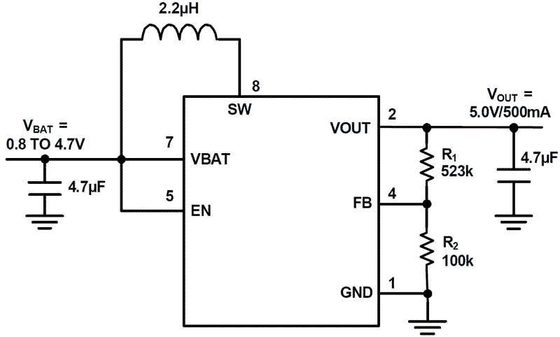
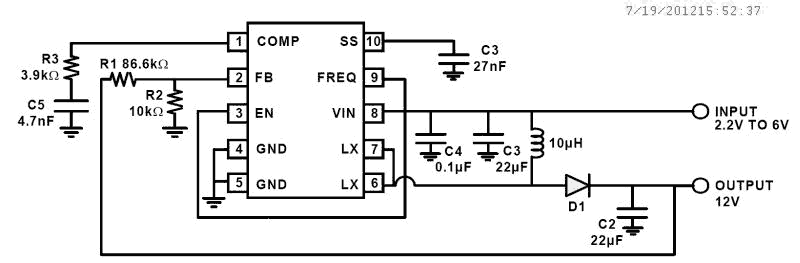
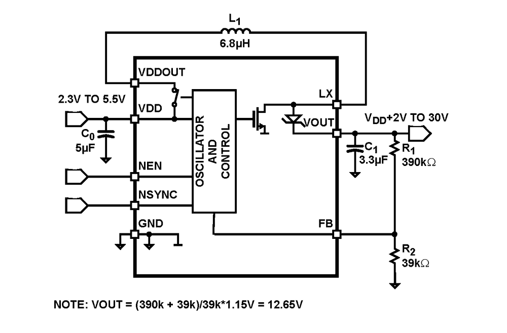
ステップアップコンバータとも呼ばれる昇圧コンバータは、入力電圧よりも大きな出力電圧を持つDC/DCパワーコンバータです。 このデバイスは、VOUTより低い電源の電圧を昇圧します。
サブカテゴリ |
Temp. Range |
Pkg. Type |
Lead Count (#) |
Pkg. Dimensions (mm) |
|
|---|---|---|---|---|---|
| 型名 | |||||
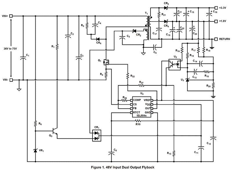
| フレキシブルシングルエンド電流モードPWMコントローラ | Flyback & Forward Controllers | -40 to +105°C | SOICN, TSSOP | 16 | 5.0 x 4.4 x 0.00, 9.9 x 3.9 x 0.00 |
| Flexible Single-ended Current Mode PWM Controller | Flyback & Forward Controllers | -40 to +105°C | QFN, TSSOP | 16 | 3.0 x 3.0 x 0.90, 5.0 x 4.4 x 0.00 |
| Flexible Single Ended Current Mode PWM Controllers | Flyback & Forward Controllers | -40 to +105°C | QFN, SOICN, TSSOP | 16 | 3.0 x 3.0 x 0.90, 5.0 x 4.4 x 0.00, 9.9 x 3.9 x 0.00 |
| Improved Industry-Standard Single-Ended PWM Controller | Flyback & Forward Controllers | -40 to +85°C | MSOP, SOICN | 8 | 3.0 x 3.0 x 0.00, 4.9 x 3.9 x 0.00 |
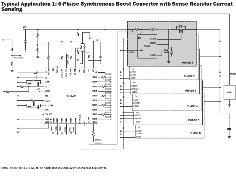
| 6-Phase Interleaved Boost PWM Controller with Light Load Efficiency Enhancement | Switching Regulators | -40 to +125°C | TQFP-EP | 44 | 10.0 x 10.0 x 0.00 |
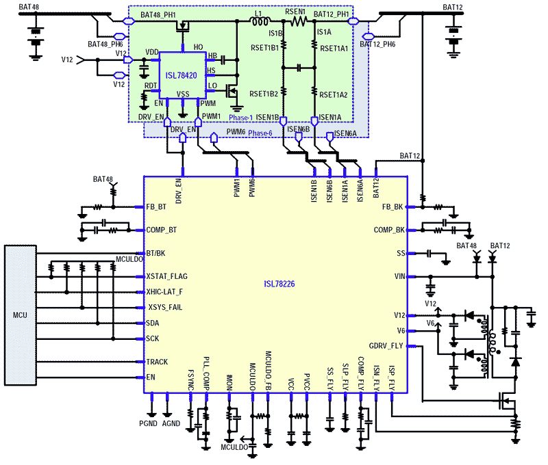
| 4-Phase 12V/48V Bidirectional Synchronous PWM Controller | Switching Regulators | TQFP-EP | 64 | 10.0 x 10.0 x 0.99 | |
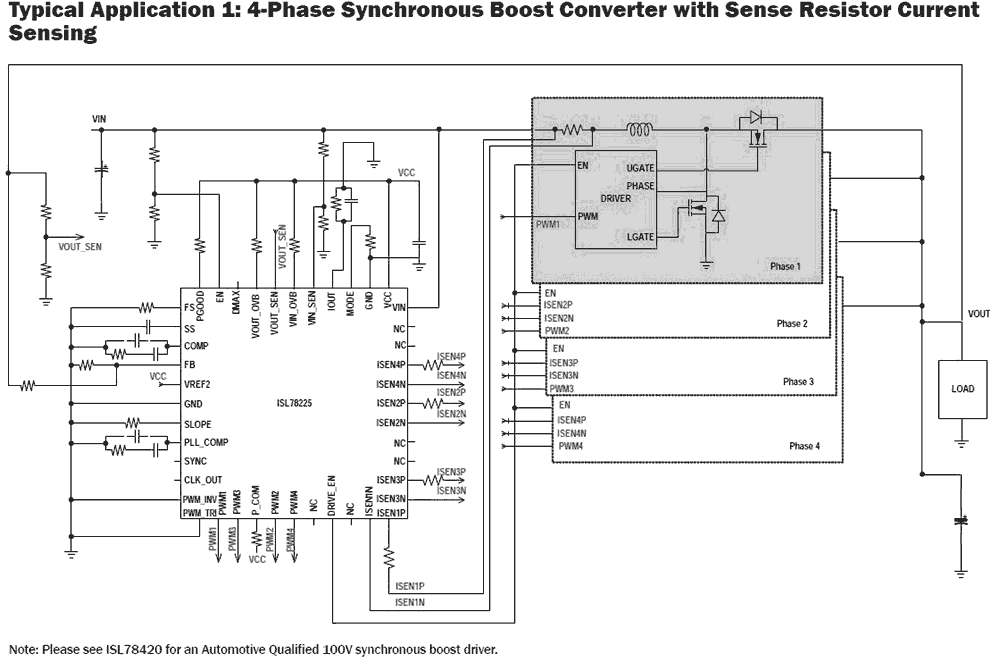
| 4-Phase Interleaved Boost PWM Controller with Light Load Efficiency Enhancement | Switching Regulators | -40 to +125°C | TQFP-EP | 44 | 10.0 x 10.0 x 0.00 |
| 6-Phase 12V/48V Bidirectional Synchronous PWM Controller | Switching Regulators | -40 to +125°C | TQFP-EP | 64 | 10.0 x 10.0 x 0.99 |
| 2-Phase Boost Controller with Integrated Drivers | Switching Regulators | -40 to +125°C | WFQFN | 32 | 5.0 x 5.0 x 0.85 |
| 2-Phase Boost Controller with Drivers and I²C/PMBus™ | Switching Regulators | -40 to +125°C | WFQFN | 40 | 6.0 x 6.0 x 0.85 |
| Advanced Single Universal Pulse-Width Modulation (PWM) Controller | Buck Controllers (External FETs) | -40 to +85°C | QFN, QSOP | 20 | 4.0 x 4.0 x 0.90, 8.6 x 3.9 x 0.00 |
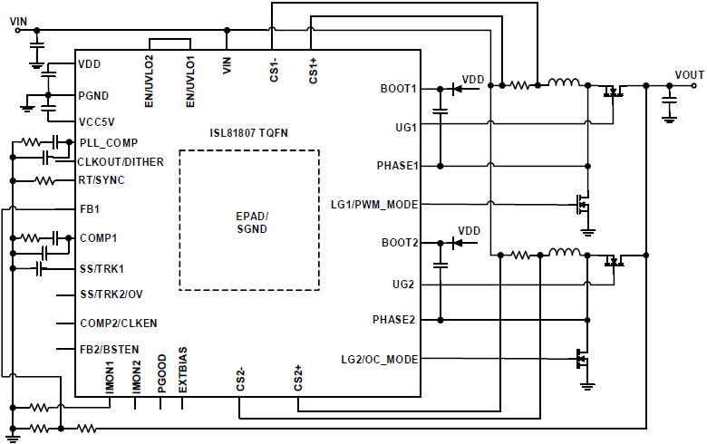
| 80Vデュアルまたは2相同期整流ブーストコントローラ | Boost Controllers (External FETs) | -40 to 125°C | TQFN | 32 | 5.0 x 5.0 x 0.75 |
| 80V Dual or 2-Phase Synchronous Boost Controller Optimized to Drive E-mode GaN FET | Boost Controllers (External FETs) | -40 to 125°C | TQFN | 32 | 5.0 x 5.0 x 0.75 |
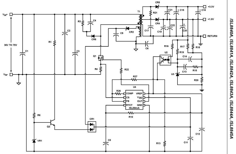
| 高性能業界標準シングルエンド電流モードPWMコントローラ | Flyback & Forward Controllers | -40 to +105°C, -55 to +125°C | MSOP, SOICN | 8 | 3.0 x 3.0 x 0.00, 4.9 x 3.9 x 0.00 |
| High Performance Industry Standard Single-Ended Current Mode PWM Controller | Harsh Environment Isolated PWM Switching Controllers | -40 to +105°C, -55 to +125°C | MSOP, SOICN | 8 | 3.0 x 3.0 x 0.00, 4.9 x 3.9 x 0.00 |
| High Performance Industry Standard Single-Ended Current Mode PWM Controller | Harsh Environment Isolated PWM Switching Controllers | -40 to +105°C, -55 to +125°C | MSOP, SOICN | 8 | 3.0 x 3.0 x 0.00, 4.9 x 3.9 x 0.00 |
| Single-Ended Current Mode PWM Controller with 3% Current Limit and Military Temp Grade Option | Harsh Environment Isolated PWM Switching Controllers | -40 to +105°C, -55 to +125°C | MSOP, SOICN | 8 | 3.0 x 3.0 x 0.00, 4.9 x 3.9 x 0.00 |
| High Performance Industry Standard Single-Ended Current Mode PWM Controller | Harsh Environment Isolated PWM Switching Controllers | -40 to +105°C, -55 to +125°C | MSOP, SOICN | 8 | 3.0 x 3.0 x 0.00, 4.9 x 3.9 x 0.00 |
| High Performance Industry Standard Single-Ended Current Mode PWM Controller | Harsh Environment Isolated PWM Switching Controllers | -40 to +105°C, -55 to +125°C | MSOP, SOICN | 8 | 3.0 x 3.0 x 0.00, 4.9 x 3.9 x 0.00 |
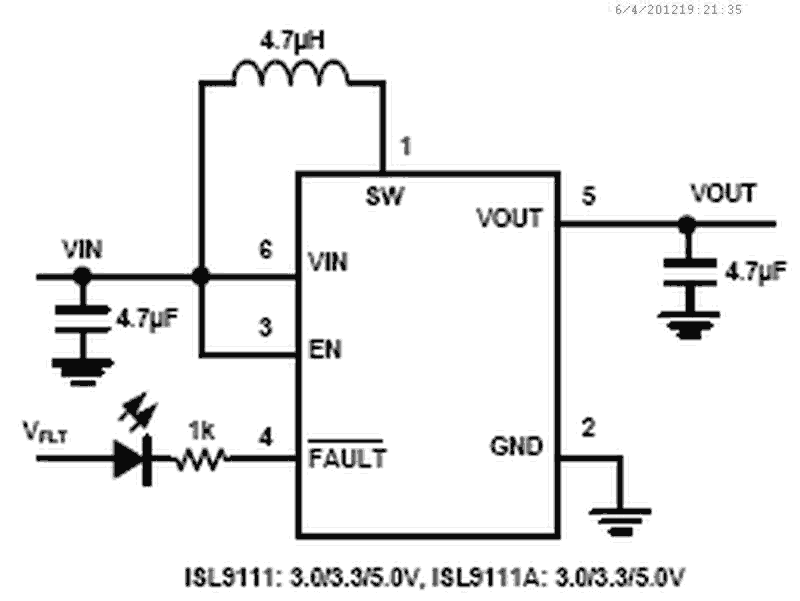
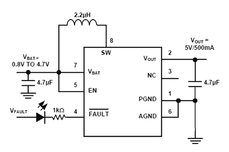
| Low Input Voltage, High Efficiency Synchronous Boost Converter with 1A Switch | Boost Regulators (Integrated FETs) | -20 to +85°C | SOT23 | 6 | 2.9 x 1.7 x 0.00 |
| High Efficiency Synchronous Boost Converter with 4.2A Switches and Output Disconnect | Boost Regulators (Integrated FETs) | -40 to +85°C | WLCSP-TKCURDLBC | 20 | 2.3 x 1.7 x 0.54 |
| 1Aスイッチ付 低入力電圧、高効率同期整流昇圧コンバータ | Boost Regulators (Integrated FETs) | -20 to +85°C | SOT23 | 6 | 2.9 x 1.7 x 0.00 |
| Low Input Voltage and High Efficiency Synchronous Boost Converter with 1.3A Switch | Boost Regulators (Integrated FETs) | -20 to +85°C | DFN, WLCSP-BP | 6, 8 | 0.8 x 1.4 x 0.00, 2.0 x 2.0 x 0.90 |
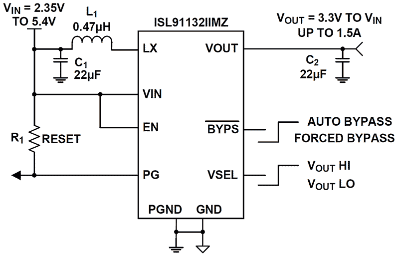
| High Efficiency 1.8A Boost Regulator with Input-to-Output Bypass | Boost Regulators (Integrated FETs) | -40 to +85°C | WLCSP-TKCURDLBC | 16 | 1.8 x 1.8 x 0.54 |
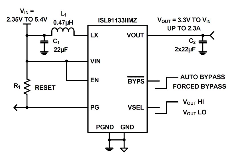
| 入出力バイパス付き、高効率2.3A昇圧レギュレータ | Boost Regulators (Integrated FETs) | -40 to +85°C | WLCSP-TKCURDLBC | 16 | 1.8 x 1.8 x 0.54 |
| High Efficiency 1.8A Boost Regulator with Input-to-Output Bypass | Boost Regulators (Integrated FETs) | -40 to +85°C | WLCSP-TKCURDLBC | 16 | 1.8 x 1.8 x 0.54 |
| 1.3Aスイッチ搭載、低入力電圧、高効率同期整流昇圧コンバータ | Boost Regulators (Integrated FETs) | -40 to +85°C | DFN | 8 | 2.0 x 2.0 x 0.90 |
| Ultra-Low IQ Boost Regulator with Bypass | DC/DC Converters | DFN | 8 | 2.0 x 3.0 x 0.90 | |
| 600kHz/1.2MHz PWM Step-Up Regulator | Boost Regulators (Integrated FETs) | -40 to +85°C | MSOP | 8 | 3.0 x 3.0 x 0.00 |
| 600kHz/1.2MHz PWMステップアップレギュレータ | Boost Regulators (Integrated FETs) | -40 to +85°C | MSOP | 8 | 3.0 x 3.0 x 0.00 |
| Integrated 4A Switch PWM Step-Up Regulator | Boost Regulators (Integrated FETs) | -40 to +85°C | TDFN | 10 | 3.0 x 3.0 x 0.75 |
| Boost Regulator with Integrated Schottky and Input Disconnect Switch | Boost Regulators (Integrated FETs) | -40 to +85°C | DFN | 10 | 3.0 x 3.0 x 0.90 |
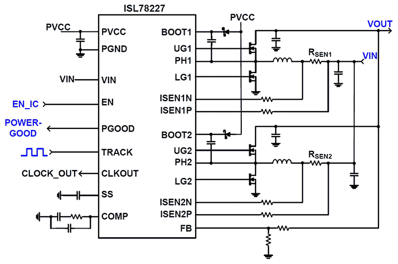
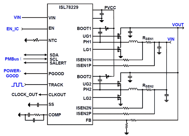
Intersil introduces ISL78227 and ISL78229 automotive-grade, 55V, 2-phase, synchronous boost controllers. The ISL78229 offers a PMBus interface for advanced control, telemetry and diagnostics. Intersil also demonstrates how these devices can offer solutions to common challenges in automotive power design.
Hi, I'm Steve Schulte, Application Engineering Manager for automotive power management products at Intersil. Today I'd like to introduce Intersil's new automotive grade boost controllers, ISL78227 and ISL78229. The ISL78229 offers a PMBus interface for advanced control, telemetry and diagnostics.
I'm going to demonstrate how these devices provide several means to solve a common challenge in automotive power supply design. Often a system needs to dynamically adjust, scale, or modulate the power supply voltage based on load demands or system needs. For example, whenever the battery supply is low, power consumption of various components, such as audio amplifiers, must be limited, especially when the engine is restarted in start/stop operation.
The ISL78227 and ISL78229 offer a unique envelope tracking feature that dynamically adjusts or scales the output voltage on the fly to meet all system load demands.
Let me show you how this works on this ISL78229 evaluation board. Here I've set up the ISL78229, with an input supply of 12V and configured the output voltage to 36V. In this configuration it is set up to deliver a 3A current to the load. In addition, I have provided an analog envelope signal to the track pin via a function generator. The tracking bandwidth of the track pin is approximately 400Hz. Here I am providing a sinusoidal envelope at 200Hz. On the oscilloscope you can see the track signal on channel 1 in yellow and the corresponding output voltage on channel 4 in green. As you can see, the output voltage is proportional to the track input and is varying between 16V and 36V.
For systems that find it more convenient to create a digital PWM signal, such as a DSP or microcontroller based system, the track pin can also follow such a signal. Here I have provided a PWM signal, whose duty cycle varies in a triangular pattern. Now I'm going to switch to the output, which is varying between 16V and 36V, in the shape defined by the duty cycle of the PWM input.
In summary, the ISL78227 and ISL78229 are easy to use and also the industry's most robust and highly integrated boost controllers. Some of the key features include: two layers of overcurrent protection prevent runaway system damage, negative current protection prevents large currents that can damage the high-side FET, average current limiting allows high current for brief heavy load periods and prevents long durations that can cause overheating, diagnostic features to aid in ASIL compliance.
We have a complete set of support tools, such as evaluation boards, user guides and a white paper.