
Reduce board footprint and BOM costs with Renesas R5 (Rapid Robust Ripple Regulator) Technology.
Key Features
- Best-in-class transient performance
- Stable operating frequency in steady-state with variable duty cycle and frequency in response to load transient
- Automatic phase adding/shedding with efficiency optimization algorithm
- Seamless, natural transition between PWM and PFM
- Low-Iq in PFM
Renesas R5 controller technology is a proprietary modulation technique that offers the fastest response to changing output load conditions. R5 is the next evolution of our unique current-mode hysteretic controller with improved bandwidth and lower Iq than previous implementations.
Using R5 results in much smaller output voltage overshoot and undershoot, resulting in a lower output capacitance. As a result, the board footprint and BOM cost can be reduced significantly.
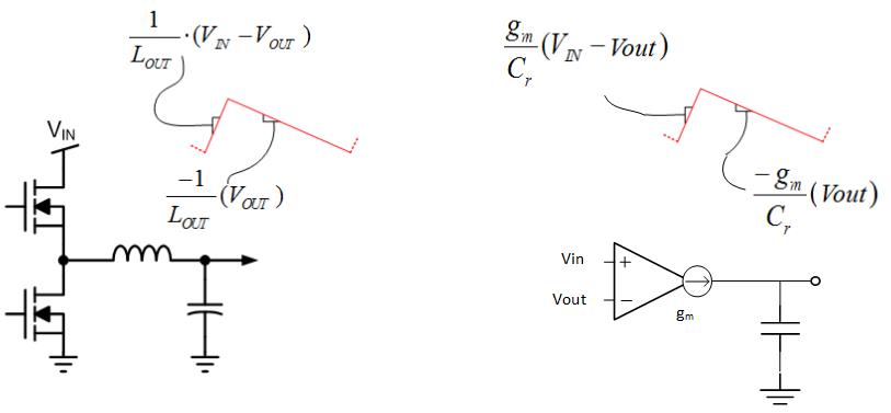
Inductor Current and Synthetic Current
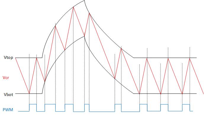
R5 Controller in Transient Condition
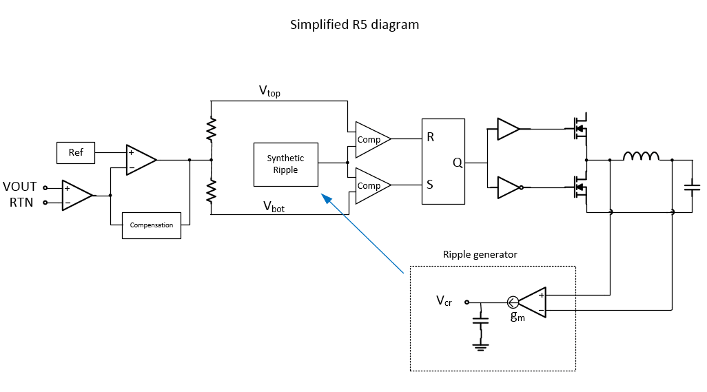
The R5 modulator operates using a hysteretic window and a synthetic current signal labeled in the diagram as Vcr. The synthetic ramp is a representation of the inductor waveform without needing to directly sense the inductor current. This helps reduce random noise/jitter on the PWM signal and in turn improves the output voltage ripple.
In steady-state, the window is controlled to maintain a constant switching frequency with consistent duty-cycle.
Since the window shifts during a transient event, both edges of the PWM pulse can be moved in time relative to their steady-state location. This allows the loop to react to dynamic loading better than a fixed frequency modulation scheme.
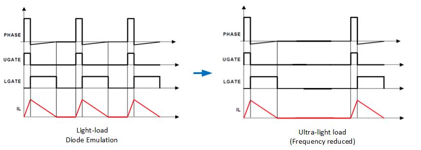
Light-load Efficiency
The R5 modulator will automatically transition into diode emulation mode to increase light-load efficiency. This means that low-side MOSFET channel will conduct when the current is from the source to drain direction, but will not allow current in the reverse direction. This emulates a non-synchronous buck with a free-wheeling diode. By preventing reverse current across the inductor, power loss can be reduced.
In addition, the R5 modulator does not rely on a fixed clock to set or reset PWM pulses. As a result, it can naturally skip pulses when necessary. When the load current is very light, the switching frequency of the loop will be lowered reducing the switching losses dramatically.
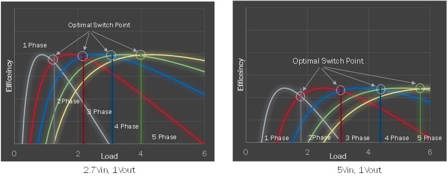
Optimized Phase Adding/Shedding
Many phase adding/shedding schemes use fixed current levels to adjust the phase count. However, this is an incomplete view of efficiency optimization. For example, the two diagrams above show the optimal switch points for a 5-phase system. Take note that the load current at which one should switch to 2-phase mode shifts from 1.2A to 1.8A when the supply voltage is raised from 2.7V to 5V.
The R5 controller uses a proprietary optimization algorithm that uses load current as well as a variety of external factors such as supply voltage, temperature, etc. to deliver highest efficiency across real world operating conditions.
See Also: R4™ Control Loop | R3™ Technology