
Renesas R3 technology (Robust Ripple Regulator) combines the best features of fixed-frequency PWM and hysteretic PWM while eliminating many of their shortcomings.
Renesas’ patented R3 modulation technology delivers acoustic noise-free operation, best-in-class light-load efficiency and fast dynamic response for longer battery life.
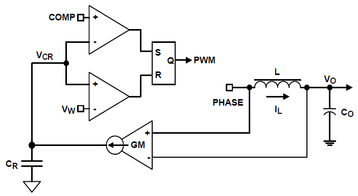
Renesas' R3 technology can simultaneously affect the PWM switching frequency and PWM duty cycle in response to input voltage and output load transients. The term “Ripple” in the name “Robust Ripple Regulator” refers to the converter output inductor ripple current, not the converter output ripple voltage. The R3 modulator synthesizes an AC signal VR, which is an ideal representation of the output inductor ripple current.
R3 Modulator Circuit Operation
Operation Principles in Steady State
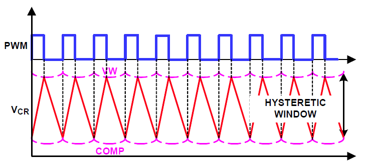
There is a fixed voltage window between VW and COMP. This voltage window is called the VW window in the following discussion. The modulator charges the ripple capacitor CR with a current source equal to gm(VIN - VO) during PWM on-time and discharges the ripple capacitor CR with a current source equal to gmVO, during PWM off-time, where gm is a gain factor. The CR voltage VCR therefore emulates the inductor current waveform. The modulator turns off the PWM pulse when VCR reaches VW and turns on the PWM pulse when it reaches COMP.
Since the modulator works with VCR, which is a large amplitude and noise free synthesized signal, it achieves lower phase jitter than conventional hysteretic mode modulator.
R3 modulator circuit operation principles during dynamic response
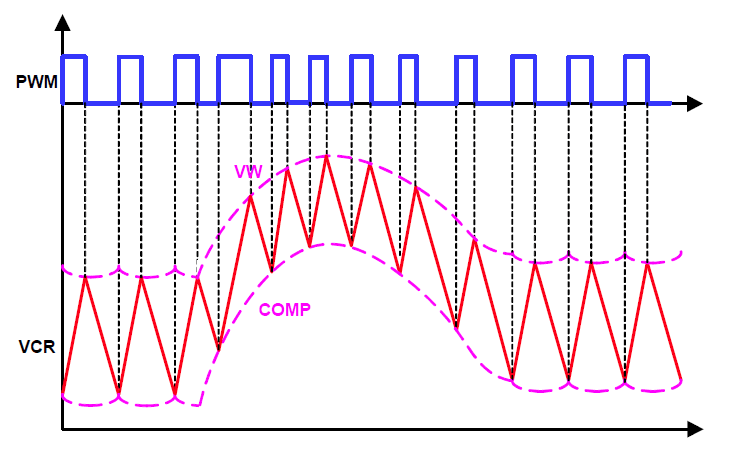
The COMP voltage rises during dynamic response, turning on PWM pulses earlier and more frequently temporarily, which allows for higher control loop bandwidth than conventional fixed frequency PWM modulator at the same steady state switching frequency.
Diode Emulation (DE) Mode
The R3 modulator can operate in diode emulation (DE) mode to increase light-load efficiency. In DE mode the low-side MOSFET conducts when the current is flowing from source-to-drain and does not allow reverse current, emulating a diode.
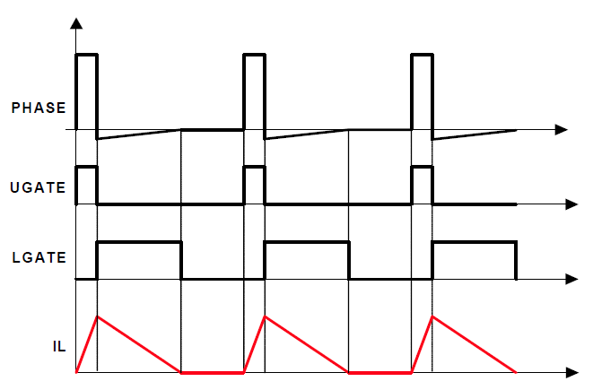
When LGATE is on, the low-side MOSFET carries current, creating negative voltage on the phase node due to the voltage drop across the ON-resistance. The IC monitors the current by monitoring the phase node voltage. It turns off LGATE when the phase node voltage reaches zero to prevent the inductor current from reversing the direction and creating unnecessary power loss.
If the load current is light enough, the inductor current will reach and stay at zero before the next phase node pulse and the regulator is in discontinuous conduction mode (DCM). If the load current is heavy enough, the inductor current will never reach 0A and the regulator is in CCM although the controller is in DE mode.
In this example, the load gets incrementally lighter in the three cases from top to bottom. The PWM on-time is determined by the VW window size, therefore is the same, making the inductor current triangle the same in the three cases.
The R3 modulator clamps the ripple capacitor voltage VCR in DE mode to make it mimic the inductor current. It takes the COMP voltage longer to hit VCR, naturally stretching the switching period. The inductor current triangles move further apart from each other, such that the inductor current average value is equal to the load current. The reduced switching frequency helps increase light-load efficiency.
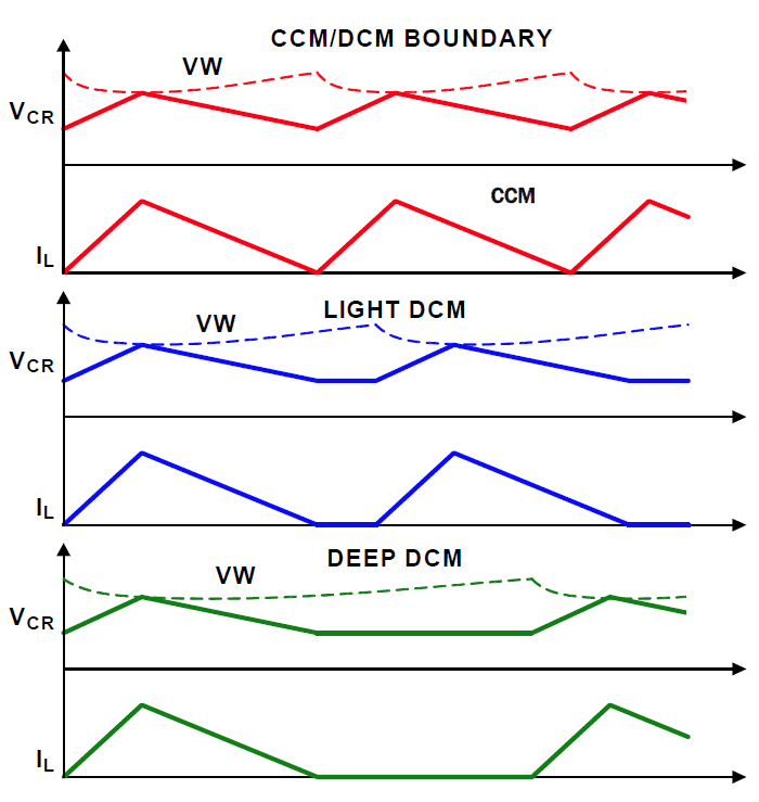
Operation Principle in Diode Emulation Mode at Light Load
See Also: R4™ Control Loop | R5™ Modulation Technology