
Get to know this life changing technology: 3 of 5
The USB PD standard allows for delivery of power up to 100W. When power is at these levels, there is always a risk that a defect in the cable or in a device may result in overheating or perhaps even fire. There is also concern that the recent influx into the market of counterfeit products may further compromise safety at higher powers. For these reasons, the USB PD standard also includes provisions to minimize the risk of accidents caused by defects or product misrepresentations.
Potential Mishaps
Safety is an important issue for designers and users of USB charging. Connecting a Micro-B plug upside down, for example, has been known to result in socket damage and burnout. The advent of USB PD makes safety an even more important concern, owing to this new standard’s support for considerably higher voltages and currents.
Cable defects are another source of concern. Resting a heavy object on a cable, for example, may damage the internal insulation, causing a short-circuit current surge that can cause a rapid rise in internal temperature.
Other types of potential failures must also be considered. As we’ve seen, USB PD allows source and sink to negotiate to select a voltage over the range of 5V to 20V. It remains possible, however, that an error along the way may result in an unexpectedly high voltage applied to the VBUS, potentially leading to overheating or fire.
Yet another concern is the recent influx into the market of counterfeit products—many of which fail to meet the relevant safety standards. These devices may operate correctly at the conventional 5V, but create problems as voltages go higher. There are, in fact, reports that the use of such products has resulted in device damage, overheating, and fire. Because these devices misrepresent themselves as quality branded products, customers can often be misled into buying them.
Designers of USB PD devices must therefore take precautions against a wide range of hazards—including those that might result from socket or cable damage, or from connection to counterfeit components. The USB PD standard itself implements a variety of protections to counter these hazards. Devices that are truly USB PD compliant can therefore be trusted to operate at a high level of safety.
Negotiation Determines Voltage and Current
Let’s consider how USB PD charging works, assuming that the device to be charged is connected by USB Type-CTMcable to an AC adapter. In particular, let’s see how this scenario successfully sidesteps some of the problems indicated above.
First, notice that there is no danger of causing damage by inserting the plug upside down, since Type-CTMplugs are flippable. So Type-CTMconnections eliminate this problem completely.
Charging begins when the cable is connected up and the AC adapter is plugged in. At this initial stage, 5V is applied to the VBUS line; the AC adapter is recognized as the source, and the device as the sink.
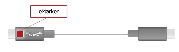
Figure 1: USB 3.1–compliant USB Type-CTMcable includes eMarker circuitry that returns information about the cable’s specifications, its manufacturer, and more.
In accordance with the USB PD standard, the source and sink now communicate. First they check to ensure that the cable itself is USB PD–compliant. This compliance information is provided by electronic marker (eMarker) circuitry built into the cable itself—implemented as an IC chip at one of the cable plugs (or by two chips, one at each plug). E-marker circuitry is included on all USB 3.1–compliant cables, and is present on some USB 2.0–compliant cables as well. This circuitry provides information about the cable’s specifications—including its maximum supported current (3A or 5A) and voltage. (See Fig. 1.) Based on this information, the sink and source can determine an appropriate voltage and current to use.
In our previous session, we presented a table showing combinations of USB PD power, voltage, and current. (Please refer to chapter (2) USB PD: The Technology, Table 1) The table shows that in cases where the voltage is 20V and the power is above 60W up to 100W, the current is limited by the cable specifications (see the table entry marked “![]() *”). These cable specifications are ascertained from the information returned by the eMarker circuitry.
*”). These cable specifications are ascertained from the information returned by the eMarker circuitry.
The source and sink proceed to negotiate to determine the appropriate power conditions in accordance with the Power Rules—taking into account the source’s capability, the sink’s desired voltage and current, and the cable. Voltage through VBUS remains at 5V until negotiation is completed, at which time the voltage is brought to the agreed-upon level and USB PD power supply begins.
Protection Circuitry
Where the cable is USB PD-compliant and the equipment is working properly, the Power Rules will ensure that the charge parameters are set within the limits of permissible voltage and current. But things are not quite safe yet, as there is still a danger that a defect in the cable or a connector may lead to operational errors, device damage, or a potential fire hazard.
Under USB PD, problems might potentially arise with any of three parameters: voltage, current, and temperature. This is why the USB PD standard also provides for the capability to detect such problems—so that operation can be stopped, or conditions adjusted, before equipment damage or fire can arise. In particular, the latest USB PD standards provide for overvoltage protection (OVP), overcurrent protection (OCP), and over-temperature protection (OTP); power supply must be reduced when any of these conditions are detected. Adherence to USB PD standards, therefore, helps ensure that effective protection is in place.
Authentication (C-AUTH)
Certified USB logos on cables and AC adapters indicate that these products are certified by the USB-IF (USB Implementers Forum). Use of certified products ensures that OVP, OCP, and OTP are implemented at both the source side and the sink side. The cable’s eMarker circuitry will also provide information about the cable’s specifications.
But there remains yet another potential hazard: the unwitting use of counterfeit products. Counterfeits may carry certified USB logos even though they are not in fact certified. Purchasers can not be sure that a product is legitimate simply by looking at the logos. And the ID information returned by a cable’s eMarker circuitry may also be counterfeited—an inferior cable may store and return ID data copied directly from a high-quality model.
There also exist malicious USB devices (“BadUSBs”) that misrepresent their capability, and are designed to cheat the user. Until recently there was no efficient way for systems to check for such malevolent devices.
| C-AUTH Result | Sink’s Behavior |
|---|---|
| Failed authentication | Request up to 500mA at 5V |
| Passed authentication; but not on whitelist | Request up to 500mA at 5V |
| Passed authentication; on whitelist | The device is authenticated and trusted. The sink can trust eMarker information, etc. |
Table 1: Sink Behaviors in Response to C-AUTH and Whitelist Search
For these reasons, the USB-IF has established USB Type-CTMAuthentication (C-AUTH)—a means for authenticating devices and thereby protecting against data tampering and illicit use. The USB PD standard implements C-AUTH through use of a public key infrastructure (PKI) which is a time-proven approach in the Internet world. We will not go into details of PKI implementation here; we will simply note that C-AUTH starts when an initiator (laptops, tablets, etc.) reads out a certificate chain from a responder (cable, AC adapter, etc.). Notice that the process can cover the cables as well as the sources and sinks, allowing for systems to be configured at a high level of safety.
For compliance testing, each manufacturer applies to the USB-IF to obtain XIDs for its products. During the USB Type-CTMAuthentication process, the initiator reads its responders’ XIDs along with other electronic certification information. Using the compliance infrastructure includes an external database (whitelist) that includes each XID together with its related compliance test status, the initiator can then check the whitelist to confirm that its responder’s XID is listed after it authenticated the responder. If the XID is listed, the initiator can be confident that the responder has passed compliance testing.
This double checking process—authentication and whitelist—make it possible to reliably identify devices and their compliance status. The sink can use the results of this checking to determine what supply parameters to request from the source (in this case, the AC adapter). Table 1 shows an example of how a sink might behave in response to each of the possible C-AUTH results. Designers of tablets, smartphones, and other sinks can implement these behaviors as they see fit.
As we can see, the USB PD standard helps ensure safety, and introduces the means to certify that devices are legitimate and compliant. USB PD designers must fully implement compliance so as to obtain certification, and it is important to support C-AUTH to ensure that devices can be properly authenticated. In our next session, we will introduce some of the Renesas products that currently implement these USB PD requirements.
Other Charging Methods
All compliant USB charging method using USB Type-CTMconnectors and cables are conventional USB battery charging, in accordance with USB Type-CTMstandards and USB PD. Any other use, however, is not provided for under USB specifications. While numerous mobile phone vendors have employed non-standard rapid charging methods, these are not permissible in USB Type-CTMimplementations. And while early USB Type-CTMspecifications allowed for the current to be increased while holding VBUS at 5V, this is no longer permitted—and devices using this approach are to be phased out by 2019.
From the beginning, USB standards prohibited VBUS voltages in excess of 5V. It is only with the advent of USB PD that use of higher voltages has become permissible.
Module List
- USB Power Delivery (1) Enhanced Convenience in USB Charging
- USB Power Delivery (2) The Technology - Convenience and Safety
- USB Power Delivery (3) USB PD Safety Implementation USB Type-CTMAuthentication (C-AUTH) of Legitimate Devices
- USB Power Delivery (4) Renesas Solutions for USB PD
- USB Power Delivery (5) Faster Development with Renesas Solutions