
Essentials of Microcontroller Use Learning about Peripherals: 3 of 6
This series offers an overview of the various peripheral functions that support effective use of MCUs. In this session, we look at how the MCU uses serial communication to communicate with external peripherals.
Parallel Connection vs. Serial Connection
As we've discussed before, the MCU functions as the "brain" of the embedded device, whereas external peripherals units as the "hands and feet". This means that the MCU must communicate with each of these units. Consider, for example, how we might connect up a sensor. The MCU's built-in GPIO (general-purpose input/output) port, explained in the first session of this series, could be used to connect eight signal lines with the sensor, enabling the sensor to send eight bits of data at a time—using up eight GPIO data pins. This type of transfer is referred to as parallel, as one full byte of data is transferred at a single time along parallel lines. (See Figure 1, left) But using eight lines to connect to a single sensor is usually a waste of resources. Is there a way to accomplish the same thing using fewer lines?
Of course there is. We can send the bits one at a time over a single data line. Because the bits are now sent in series, we call this serial communication. (See Figure 1, right) Note, however, that the MCU uses parallel communication for its internal processing and communication. This means that the MCU must also handle the necessary conversions: "serial-to-parallel" conversion of data received from the sensor, and "parallel-to-serial" conversion of data being sent out to the sensor. On the RX63N, these conversions are handled by the SCI (serial communications interface).
To sum up: assume that we wish to send a single text character, which requires that we send an eight- bit char-type value. If we use parallel transfer, we need one data line for each bit. With serial parallel, we send the eight data bits one after another, over the same single line.
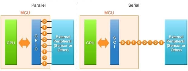
Figure 1: Parallel and Serial Communication
Clearly, serial communication requires fewer pins and wires. In today's world, most MCU-to-peripheral connections are serial. Serial mode is used not just for communication with switches and from ON/OFF sensors, but also by the GPIO to output software-generated motor-drive signals, LED flashing signals, and more.
Built-in UART Enables Easy Serial Communication
Serial communication can be implemented in numerous ways, in accordance with varying electrical characteristics and the requirements of differing protocols. The simplest implementation—requiring only a single wire—is referred to as "start-stop synchronous communication." This mode is often used when communicating with wireless LAN modules and drive monitors.
In start-stop synchronous communication, data is sent in character units1. For control purposes, a start bit is placed at the beginning of each set, and a stop bit is placed at the end. (See Figure 2) This eliminates the need to control transfer timing through use of a separate clock signal line—as required in other common serial modes, such as I2C ("I squared C") and SPI (serial parallel interface). To help ensure transfer accuracy, start/stop data sets can also include a parity bit2.
Start-stop synchronous communication is handled by a component called a "UART" (universal asynchronous receiver/transmitter). The RX63N's built-in SCI includes a UART for this purpose.
1. In start-stop synchronous communication, usually data is sent from the Least Significant Bit (LSB) (= smallest binary bit value)
2. A bit appended to each (7- or 8-bit) data set. If using even parity, the parity bit is set so that the total number of 1s (in most implementations) is even: if the data value has an odd number of 1s, the parity bit is set to 1; if the data value has an even number of 1s, the parity bit is set to 0. The receiving side will therefore know an error has occurred if it receives a data set with an odd number of 1s. Similarly, if using odd parity, the parity bit is set so that the number of 1s will always be odd.
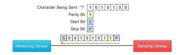
Figure 2: Start-stop synchronous communication
Start-stop synchronous communication can be implemented as either full duplex or half duplex. With full duplex, two lines are used: one for communication from the MCU to the peripheral, and the other for communication going the other way. This means that communication can go in both directions at the same time. With half-duplex, a single line is used, so that communication can only go one way at a time. The direction is changed by operating a switch. (See Figure 3)
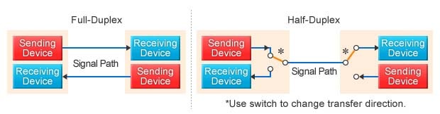
Figure 3: Full-Duplex vs. Half-Duplex
Trying It Out: Communicating with a Computer
Once again, we turn to the GR-SAKURA. This time, we will run a sample program that will enable communication between the GR-SAKURA and a terminal emulator on your personal computer. Specifically, the program will operate as follows: When the terminal emulator sends a "?" character, the GR-SAKURA board will return the character string "GR-SAKURA". Note that, in order to use this program, your computer must be running a terminal emulator. If you are using a Windows machine, you can install and use the free TeraTerm emulator, or use another emulator of your choice. On Mac machines, you can use the built-in "Terminal" program.
Note that the sample program makes use of the Serial class, which is available from the GR-SAKURA's Sakura library. This class supports full-duplex start-stop synchronous communication.
Line 8 of the code begins the serial communication, via USB. Line 13 causes the GR-SAKURA to read the character data from the computer and determine whether it is a "?" character. If so, the GR-SAKURA then returns "GR-SAKURA" to the computer. During execution, processing within the RX63N (the MCU) proceeds as follows: The SCI receives each serial data value from the computer and converts it into parallel form; the CPU checks whether the value is "?"; if it is, the CPU returns the "GR-SAKURA" string via the SCI, which converts the parallel string data into serial form and outputs the result to the computer.
This very simple program is sufficient to send character information in both directions between the computer and the GR-SAKURA. Although our example sends only the predefined string "GR-SAKURA," we encourage you to try expanding the program so that the return string varies according to whatever conditions you decide to set.
SAKURA Sketch Reference: Sakura Library "Serial Communication"
1 2 3 4 5 6 7 8 9 10 11 12 13 14 15 16 | /*GR-SAKURA Sketch Template Version: V1.08*/ #include <rxduino.h> #define SPEED 9600 //Set transfer speed to 9600 bps void setup() { Serial.begin( SPEED, SCI_USB0); //Set serial channel speed. Set serial transfer to use USB port. } void loop() { if( Serial.read() == '?') //Check if incoming character is "?" Serial.println( "GR-SAKURA"); //If so, return string "GR-SAKURA" } |
Figure 4: Sample program: When the terminal emulator sends a "?" character,
the GR-SAKURA board will return the character string "GR-SAKURA".
*Text following "//" is a comment, and does not affect the execution of the program.
*The purpose of this program is for understanding the principle. It is not sufficient for a full implementation.
If you have any problems using the TeraTerm emulator, feel free to visit the following website.
In our next session, we will look at interrupts. We look forward to seeing you then.