
Buck-Boost Narrow VDC Battery Charger with SMBus Interface and USB OTG Evaluation Board
Jump to Page Section:
Overview
Description
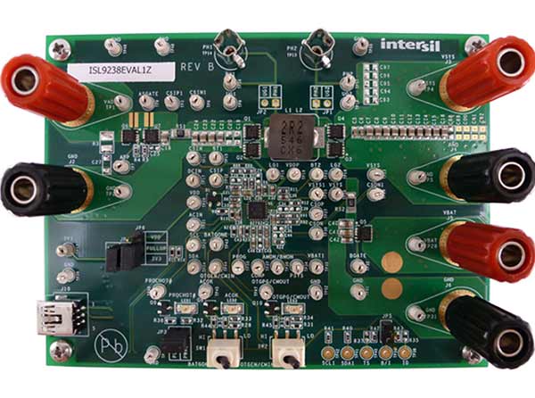
The ISL9238EVAL1Z evaluation board is designed to demonstrate the performance of the ISL9238 buck-boost Narrow Output Voltage DC (NVDC) charger. The default value numbers of the battery in series, the switching frequency and the adapter current limit charging function can be programmed by the resistor from the PROG pin to GND. Those values also can be set by SMBus.
The ISL9238 buck-boost battery charger utilizes Renesas' advanced R3™ Technology to provide high light-load efficiency, fast transient response and seamless DCM/CCM transitions for a variety of mobile and industrial applications.
In charge mode, the ISL9238 takes input power from a wide range (4V to 20V) of DC power sources (conventional AC/DC charger adapters, USB PD ports, travel adapters, etc.) and safely charges battery packs with up to 4 cells in a series configuration.
The ISL9238 supports On-the-Go (OTG) function for 2- and 4-cell battery applications. When the OTG function is enabled, the ISL9238 operates in the reverse buck mode to provide 5V at the USB port.
The ISL9238 has serial communication via SMBus/I2C that allows programming of many critical parameters to deliver a customized solution. These programming parameters include, but are not limited to: adapter current limit, charger current limit, system voltage setting, and trickle charging current limit.
Features
- Buck-boost NVDC charger for 1-, 2-, 3-, 4-cell Li-ion batteries
- End of Charge (EOC) option
- System power monitor PSYS output, IMVP-8 compliant
- PROCHOT# open-drain output, IMVP-8 compliant
- Allows trickle charging of depleted battery
- Optional ASGATE FET control
- Ideal diode control in turbo mode
- Reverse buck, boost and buck-boost operation from battery
- Two-level adapter current limit available
- Battery ship mode option
- SMBus and auto-increment I2C compatible
Applications
Applications
- 1- to 4-cell tablet, ultrabook, notebook, power bank, and any USB-C interface portable device requiring batteries
Documentation
= Featured Documentation
Log in required to subscribe
|
|
|
|
|---|---|---|
| Type | Title | Date |
| Manual - Development Tools | PDF 1.78 MB | |
| Datasheet | PDF 2.19 MB | |
2 items
|
||
Design & Development
Processing table
ISL9238EVAL1Z Active Samples Available |
Get Samples, |
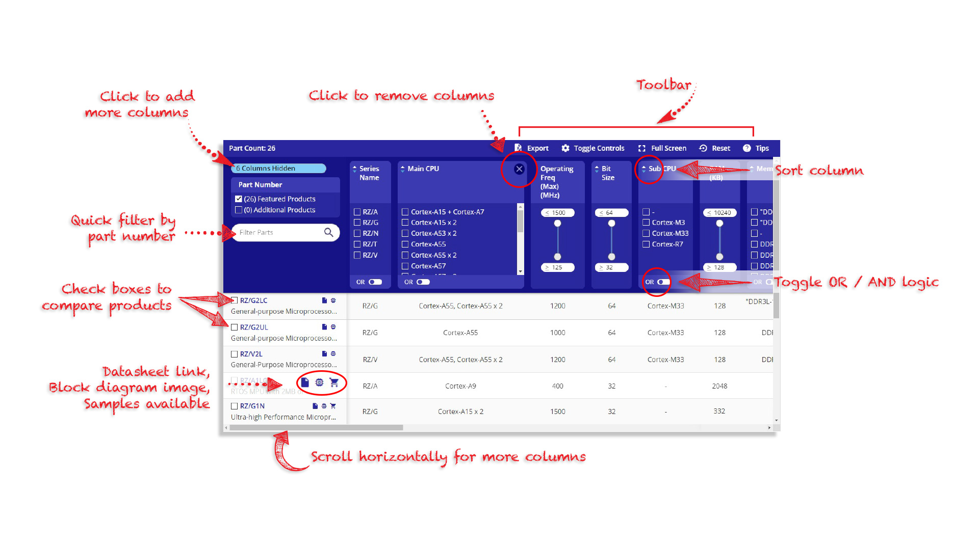
Tips for Using This Parametric Table:
- Hide Filters button in header: Collapse or expands filters
- Column sort buttons in header: Sort Column alphabetically / numerically descending or ascending
- Reset button in header: Reset all filters to the page default
- Full Screen button in header: Expand the table to full screen view (user must close out of full screen before they can interact with rest of page)
- Export button in header: Export the filtered results of the table to an Excel document
- Filter parts search bar in header: Type to filter table results by part number
- Hide column button in column headers: Select to hide columns in table
- AND / OR toggle switches in header: Toggles the logic of this particular filter to be “AND” or “OR” logic for filtering results
- Multiselect checkboxes at beginning of each row in table: Select these checkboxes to compare products against each other
- Document icon next to product name in row: View the featured document for this product
- Chip icon next to the right of the document icon in row: View the block diagram for this product
- Cart icon to the right of the chip icon: Indicates that samples are available for this product
Videos & Training
Evaluating the ISL9238, ISL9237 Buck-Boost Battery Chargers
Learn how to set up the ISL9237 evaluation board and connect the EVB to the GUI interface. Add an electrical load and measure output voltage and phase voltages without the need for a Li-Ion battery or emulator.
Transcript
ISL9237 Evaluation Board and GUI Demonstration
Hi, I'm Phil Brinkley, Central Applications Engineer with Intersil. Today I'd like to talk to you about the ISL9237 Eval Kit. When your order the kit, you'll receive a box like this one. In the box, it contains the board itself, USB stick with the necessary software, and some documentation on the user's manual for the board itself. You'll want to load the software, but for now I'm going to begin by demonstrating without the need of the software.
So what you need for the first part to check out and make sure your board is actually working is the board, you need a power supply, and some cabling, and oscilloscope nice to have but not necessary, and you need a multimeter.
Measure Output Voltage
So what we first want to do is connect the power supply to the board. Do that by connecting the ground to J2. And the positive to J1.
I'm going to turn my power supply on, and connect it to 5V.
As soon as you have it up and running, and the output is set to 5V. I'm going to measure the output voltage across VSYS, that is the upper right hand output connectors on the right. J3 and J4, and it should measure 8.39V or 8.38V somewhere in that neighborhood, if so, the board is working properly.
The second thing you can do without having to load any of the software is to add an oscilloscope in, and measure the phase voltages. So I'm measuring phase one, and phase two on the ISL9237 itself. So what I'm going to do now is increment my voltage output from 5V in, all the way up to about 15V, and then back down. As I do, you'll see the phase voltages change, and that will indicate the difference between boost mode, because right now we have 5V coming in, and 8V coming out, or more than 8V coming out.
We're on boost mode, and then it's going to move into buck-boost mode, and eventually move into buck mode.
And so you want to see that if you have an oscilloscope, you can just slowly ramp the voltage up.
When I get to about 7V or 8V, it begins to move into buck-boost mode. I started off in the boost mode, and when I get above 11V or so. It'll move into pure buck mode. So you can see the phases change.
So those two things are easy to do right out of the box, and you can make sure your board is working.
Using ISL9237EVAL2Z GUI Software
Next thing you can do is add the software piece in. You'll find that under start button, all programs, Intersil, and then the program name itself is called ISL9237 SMBus tool C3.
If you have any issues installing the software, go to the ISL9237 product page, click under the resources tab, we have some FAQs, they help walk you through, maybe issues that you might run into a driver or such.
We need a mini USB cable. Plug the cable in to the board. Once you have that connected, you want to make sure that your computer is talking over USB to the ISL9237.
So you want to confirm on the upper right hand corner of the software that you have a green check mark. Right now, I have a red X box, so it means it's not connected. So I'm going to click on reset USB. And in my case everything is connected right, and the green check mark is now on.
To verify that your software is connected actually to your board, go to manufacturer ID, click read, and you should see 0049 for manufacturer ID. That's identified in the datasheet.
Last thing you might want to try is to add a load to the output. Now loads can be a lot of different things, if you have a battery emulator that would be probably one of the best things you could use. You might actually power a rechargeable lithium ion battery. In my case, I'm just going to use a 1Ω power resistor. It's a cheap and dirty way to make sure that the device is doing what you think it's doing.
So I'm going to connect that to the VBAT, which is the bottom right hand output connector. It's J5 and J6.
In the software, choose one cell under battery cell configuration. I'm going to hit right all and then I'm going to measure the voltage across the battery which is the power resistor.
Right now, I'm reading 0V, that's to be expected because the default in the software is 0A on the charge current limit. If I change the charge current limit to say something like 1A, and click write all, the output voltage jumps to 1V, makes sense. I've got a 1Ω resistor, and I'm feeding 1A through it. I have 1V across.
So that demonstrates getting started quickly with the ISL9237 Eval Kit. There's a lot of different things you can do in the software, and with the kit. Go to our website and refer to the user's manual for further demos that can be done with this. Thanks for watching.
Video List