

Modern vehicles are equipped with an increasing number of sensors that are widely distributed within the car. Each of them requires a data connection to its control unit but also a power supply to operate. Since the wiring harness is the 3rd heaviest component in a car (after chassis and engine), any attempt to reduce its weight, size, and cost is very welcome. So why not use the same pair of cables for data and power? The power consumption of a sensor is comparably small it is very much suitable for a technology called Power over Data Line
Power over Data Line (PoDL) History/Background
The basic idea is always to send power and communication over the same line to save costs and space. For this, the IEEE released the standard 802.3af in 2009, which is called Power over Ethernet (PoE) and is probably even used at your home or office (for example, IP desk phone, IP camera, etc.). But for this, at least two pairs of wires are needed which are not available with single pair Ethernet. Therefore, the IEEE published the standard IEEE 802.3bu in 2016 to transmit power over only one data pair, which is called Power over Data Line (PoDL). There are also solutions available that use an opposite concept, data over powerline, which is widely used in metering and building management systems.
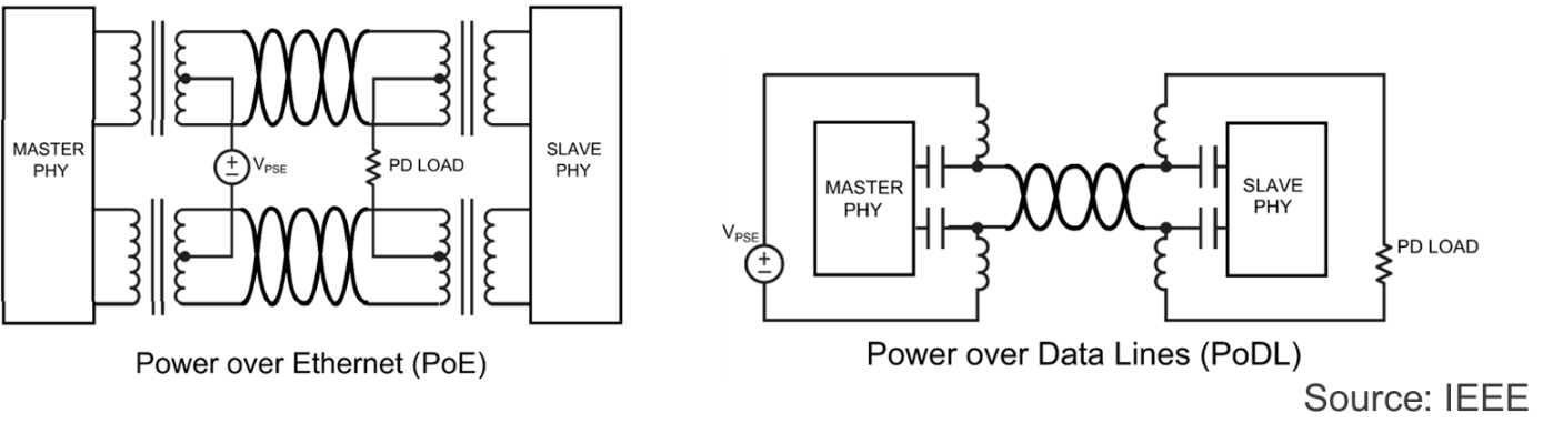
The most important requirement for Power over Data Line is that it is possible to mix power and data transmission first and separate them later without affecting each other. PoE requires at least two pairs to work. The power lines are connected between the pair center tap of the coils. PoDL requires only one pair and the power is connected with a lowpass/highpass band splitting network, refer to Figure 1.
PoDL in a Nutshell
The Power over Data Line system consists of two devices: the Power Sourcing Equipment (PSE) which supplies the power and the Powered Device (PD) which consumes the power. To these parts a control function (application) is connected, this could be a radar sensor fusion unit task on the PSE side and a radar sensor on the PD side, or any other application.
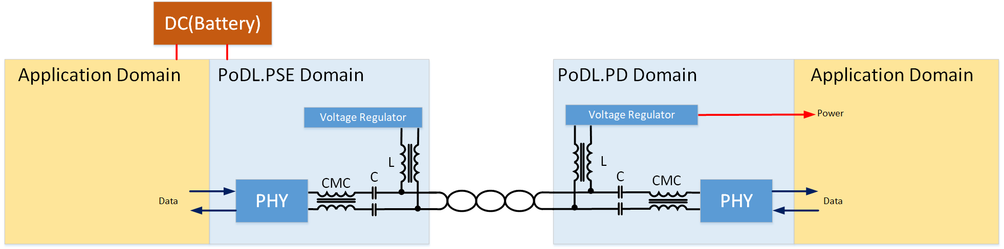
The coupling component is built by inductive and capacitive elements. Inductors allow DC current to pass with very low resistance while blocking high-frequency data streams with a very high impedance. The capacitors do exactly the opposite, they block DC currents and let high-frequency data streams pass.
In addition, the MDI Link circuit uses Common Mode Choke (CMC) to reduce the impact of common mode interference on differential signals. This CMC could be located before or after the L-C-coupling circuit. The advantage of having the CMC before (as shown in Figure 2) is that the current transferred from the PSE to the PD does not have to flow through the CMC and the CMC can be the same, whether PoDL is used or not. If the CMC is after the L-C-coupling circuit then the current of the power supply flows through the CMC. An advantage of this approach is that the CMC could improve the symmetry behavior of the power injection [2].
PoDL is currently supported for several IEEE PHY standards. The usage of PHYs in the PoDL system are categorized into types depending on the supported IEEE PHY standards. The power sourcing and powered device must be compatible with the selected type
| Type | 10BASE-T1S | 10BASE-T1L | 100BASE-T1 | 1000BASE-T1 | >2.5GBASE-T1 |
|---|---|---|---|---|---|
| A | X | X | |||
| B | X | ||||
| C | X | X | X | ||
| D | Incompatible with IEEE 802.3 PHY | ||||
| E | X | ||||
| F | X | ||||
Different applications have different power requirements. The IEEE has defined power classes to serve different power requirements. Clause 104 of IEEE 802.3 was recently expanded for 10BASE-T1S/T1L by additional classes 10 to 15 without categorizing them into unregulated and regulated PSE modules.
| 12V unregulated PSE | 12V regulated PSE | 24V unregulated PSE | 24V regulated PSE | 48V regulated PSE | 802.3cg (10BASE-T1x) | |||||||||||
|---|---|---|---|---|---|---|---|---|---|---|---|---|---|---|---|---|
| Class | 0 | 1 | 2 | 3 | 4 | 5 | 6 | 7 | 8 | 9 | 10 | 11 | 12 | 13 | 14 | 15 |
| VPSE(max) (V) | 18 | 118 | 18 | 18 | 36 | 36 | 36 | 36 | 60 | 60 | 30 | 30 | 30 | 58 | 58 | 58 |
| VPSE_OC(min) (V) | 6 | 6 | 14.4 | 14.4 | 12 | 12 | 26 | 26 | 48 | 48 | 20 | 20 | 20 | 50 | 50 | 50 |
| VPSE(min) (V) | 5.6 | 5.77 | 14.4 | 14.4 | 11.7 | 11.7 | 26 | 26 | 48 | 48 | 20 | 20 | 20 | 50 | 50 | 50 |
| IPI(max) (mA) | 101 | 227 | 249 | 471 | 97 | 339 | 215 | 461 | 735 | 1360 | 92 | 240 | 632 | 231 | 600 | 1579 |
| PClass(min) (W) | 0.566 | 1.31 | 3.59 | 6.79 | 1.14 | 3.97 | 5.59 | 12 | 35.3 | 65.3 | 1.85 | 4.8 | 12.63 | 11.54 | 30 | 79 |
| VPD(min) (V) | 4.94 | 4.41 | 12 | 10.6 | 10.3 | 8.86 | 23.3 | 21.7 | 40.8 | 36.7 | 14 | 14 | 14 | 35 | 35 | 35 |
| PPD(max) (W) | 0.5 | 1 | 3 | 5 | 1 | 3 | 5 | 10 | 30 | 50 | 1.23 | 3.2 | 8.4 | 7.7 | 20 | 52 |
The PoDL system can be implemented in different ways: unmanaged and managed. In the unmanaged case, it is basically a fully engineered setup. This is typically the case in automotive where the used class is already known. The major constraints are known and can be used accordingly. In an industrial use case where the connected device could be unknown a managed implementation has to be used. In this case, the PSE and PD device are negotiating the capabilities – which power class is connected by PD and if the PSE could support this class. If this matches, the PSE can be activated, otherwise, the PSE will not enter into the power mode.
The PoDL system follows for operation the basic flow shown in the diagram below. This flow covers all states from initialization, power up, and power down or overload cases. This flow is implemented in the PSE device, the PD device is more of a passive responder device. If the PoDL system is enabled, then the state SIGNATURE DETECTION is entered. This state is to check if a PoDL PD device is connected. The PSE will provide a constant current of 9 to 16 mA with an open circuit voltage of 4.75V to 5.5V. The PD should be recognized as valid when the sense voltage is between 4.05V and 4.7V. This valid signature can be simply generated by a Zener diode on the PD device.
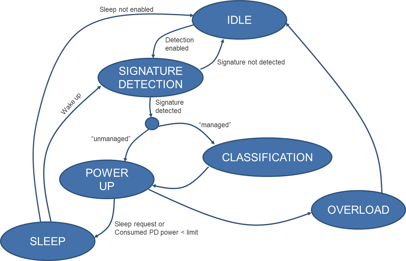
If this is the case, it can switch to the next state either POWER UP or CLASSIFICATION. The CLASSIFICATION is an optional state where the PSE and PD share information via the Serial Communication Classification Protocol (SCCP) about required power classes. The SCCP is a 1-Wire serial protocol with fairly low speed (333bps). The CLASSIFICATION is only an optional step, and reasonable if different unknown types of PD are connected to a PSE module. In an engineered network such as an automotive network, this step can be skipped, and the next state will be POWER UP.
In POWER UP state the PSE ramps up the voltage to the defined class. The PSE continues to observe the current and protects the PD from draining too much power. This observation is called “maintain full voltage signature” (MVFS), where PSE cyclically checks if the PD draws a current of more than 11mA. For instance, it could happen that the cable is disconnected, or the PD device went to power off mode. If this is the case, then PSE can stop providing power.
It then enters the state SLEEP, if sleep mode is not enabled then the state machine enters IDLE for restart or stop. If sleep is enabled, then the PSE side should remain in SLEEP and reduce the output voltage of 3.15V to 3.575V. The PSE shall transition from the SLEEP state to the SIGNATURE DETECTION state when a valid Wake-up current is detected by the PSE. Then in SIGNATURE DETECTION, the flow starts again.
The system is protected against overload, for example, if a short circuit occurs on the PD side and the PD draws too much current, the PSE will cut off the voltage for safety reasons. This overload observation is done while in POWER UP state and in case of overload detection the PSE entered the state OVERLOAD.
The description above describes only the principal workflow of the PoDL System. The actual implementation has several additional constraints to consider, for example, the power ramp up has to follow a special timing to not cause too much inrush current. Or the signature detection must be finished in the maximum time frame. For exact details, check the Clause 104 of IEEE 802.3-2022.
Conclusion
Reducing energy consumption is very important in the automotive arena since this directly influences the CO2 emissions per vehicle. Transmitting power with the data communication helps to reduce the weight and complexity of the harness. Furthermore, installation space in the vehicle is limited, and if fewer cables are used (as well less pins at the connectors), it helps to simplify the installation and keeps space for other applications. However, this technique is not new to the automotive industry since Power over Coaxial supports this already and has been used for years for camera applications. Now with PoDL, this technology can be extended to other applications that use Ethernet as a physical layer.
There is no typical use case as basically any use case in the automotive could utilize this as long as the electronics has a sufficiently low power consumption (see power class), and the power supply is stable and reliable.
However, it must be mentioned that special safety requirements must be met for automotive applications such as overtemperature, overcurrent, and overvoltage event detection and flagging. These have to be considered by the ECU development, and these requirements could be different for PSE and PD side.
Since automotive applications require fast startup and the connected devices are usually known in advance, we see no benefit in using the slow SCCP protocol and recommend not using it.
The IEEE 802.3 clause 104 does not specify PoDL for multidrop links, it is only specified for point-to-point links. The problem with multidrop is that if a communication is already established between two partners and another one wakes up, the line behavior changes dynamically, and the existing communication is disturbed.
If all wake up "at the same time" and the inrush current remains within the limits, then PoDL should also work technically on multidrop. But if this could fulfill all safety requirements is a question mark.
The Single Pair Ethernet (SPE) technology was developed for automotive, but it is just as important in the industrial area. In the past fieldbuses like CAN have dominated the machinery. But nowadays even this domain has to be compatible with Ethernet. At the same time, it should be cost-effective and space-saving, because in many machines the space is limited like in vehicles. Hence PoDL together with SPE could open new applications in the industrial area. These applications have slightly different requirements. The cable length is often much longer, not rarely over 100m, the maximum specified length is 1000m for PoDL. Further, the required power is often higher than in automotive, at 48V a maximum of 50W can be realized, which is reasonable for many applications.
What Next?
We have introduced the Power over Data Line concept in this blog and mentioned the advantages of why it makes sense to use it. In another blog, we will introduce a PoDL solution serving a radar application use case based on Renesas chipsets. This will explain how we have realized it and how you can replicate it, so stay tuned.
References
[1] IEEE 802.3-2022
[2] Automotive High Speed Communication Technologies (Kirsten Matheus; Michael Kaindl)