
Overview
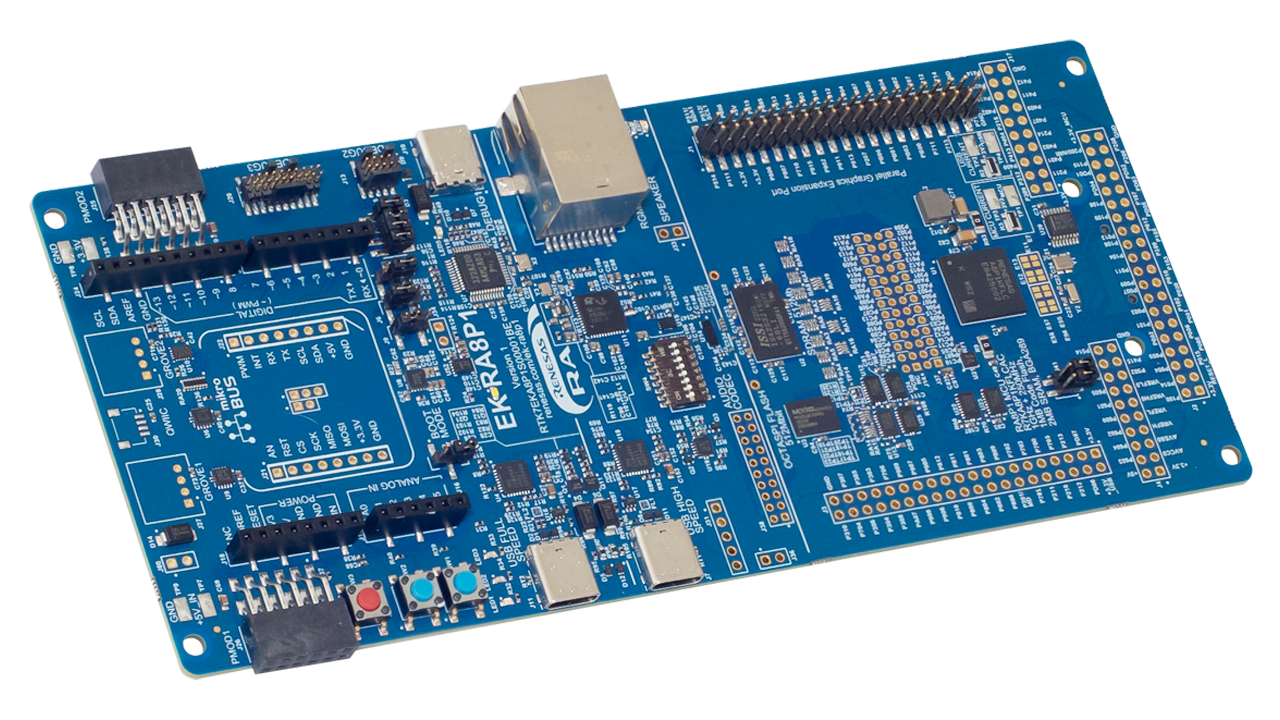
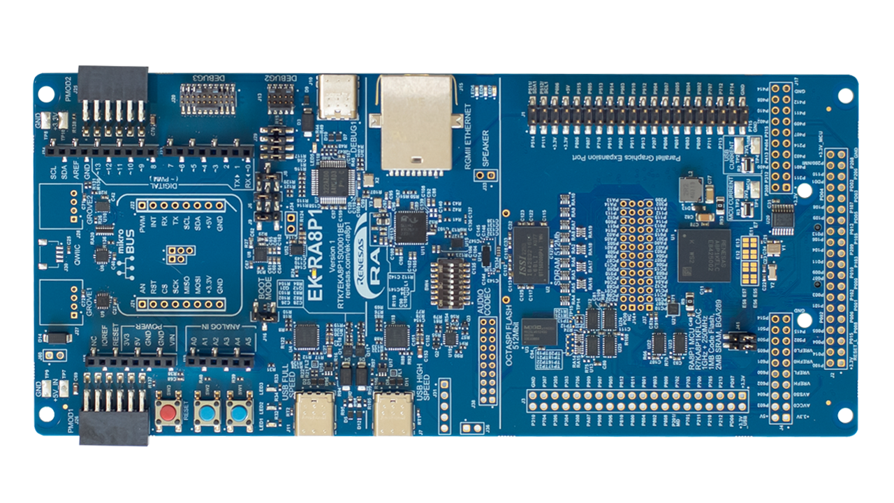
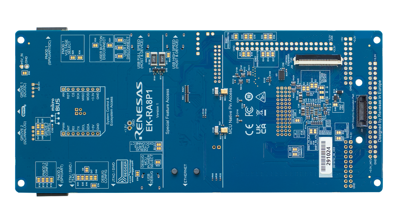
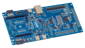
The EK-RA8P1 evaluation kit is designed to enable users to easily evaluate the RA8P1 MCU features and develop embedded system applications using Renesas' Flexible Software Package (FSP) and e2 studio IDE. Users can utilize the rich onboard features and their choice of popular ecosystem add-ons to implement a broad range of applications, including artificial intelligence (AI) and the Internet of Things (IoT). A bundle of example projects is available for users to download and quickly evaluate key peripherals to accelerate the proof-of-concept development.
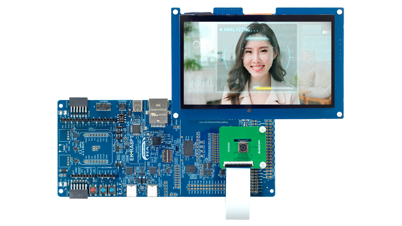
This kit is packed with a 7.0-inch, 1024x600 parallel LCD board and a 5Mpx camera module. Preloaded demonstrations that showcase the excellent performance of the RA8P1 can be found within the kit. Combine the LCD board and camera module with the EK-RA8P1 board to enable rapid voice, vision, and real-time analytics AI developments.
Features
- MCU Native Pin Access Area
- R7KA8P1KFLCAC MCU
- 1GHz, Arm® Cortex®-M85 core
- 250MHz, Arm Cortex-M33 core
- 1MB MRAM, 2MB SRAM with ECC
- 289 pins, BGA package, 12mm x 12mm x 1.38mm, 0.65mm pitch
- Native pin access through 2 x 20-pin, and 2 x 40-pin headers
- Camera expansion connector
- 2-lane MIPI display connector
- Parallel graphics display interface connector
- MCU current measurement
- R7KA8P1KFLCAC MCU
- Special Feature Access Area
- Ethernet (RGMII)
- USB High Speed Host and Device
- 64MB External Octo-SPI Flash
- 64MB SDRAM
- PDM MEMS microphones
- Audio codec with speaker out connections
- Ecosystem & System Control Access Area
- USB Full Speed Host and Device
- Multiple 5V input sources
- USB (Debug, Full Speed, High Speed)
- External power supply
- SEGGER J-Link™ on-board programmer and debugger
- Debug modes
- Debug on-board (SWD and JTAG)
- Debug in (ETM, SWD, SWO, and JTAG)
- Debug out (SWD, SWO, and JTAG)
- User LEDs and buttons
- Three user LEDs (red, blue, green)
- Power LED indicating availability of regulated power (white)
- Debug LED indicating the debug connection (yellow)
- Two user buttons
- One reset button
- Five most popular ecosystem expansions
- MikroElektronika™ mikroBUS connector
- SparkFun® Qwiic® connector *not populated
- Two SeeedGrove® system (I2C and Analog) connectors *not populated
- Two Digilent Pmod™ (SPI/UART/I2C) connectors
- Arduino™ (Uno R3) connector
- MCU boot configuration jumper
- MIPI Graphics Expansion Board
- 7.0 Inch backlit TFT display, 18.7M display colors
- 1024x600 pixels resolution
- Capacitive touch overlay (I2C)
- Camera Expansion Board
- Off-the-shelf Arducam CMOS OV5640 Camera Module
- ¼ Inch 5.0 Megapixel image sensor
- Up to 15fps in QXSGA (2592x1944 pixels) resolution
- Kit Contents: EK-RA8P1 board, MIPI graphics expansion board, camera expansion board, USB device cables (TypeC-to-TypeC, TypeA-to-TypeC , TypeA-to-TypeC female), Ethernet patch cable, camera FFC cable, and mounting hardware

Getting Started
Explore Ready-to-Run Solutions
Sample & Buy
RTK7EKA8P1S01001BE
Active| HTS (US): | 8471.50.0150 |
| ECCN (US): | 3A991.a.2 |
| SPQ: | 1 |
| Pb (Lead) Free: | No |
| Assembly Location: | CHINA |
Videos & Training
Take the guesswork out of your innovation experience by following a systematic and methodical approach to start developing with Renesas Advanced microcontrollers kits. It allows for a structured and orderly exploration of resources that you can utilize to create smart IoT and embedded products.
Additional Videos
News & Blog Posts
News Jul 1, 2025 |
Blog Post Jan 28, 2022 |
Blog Post Jan 28, 2022 |
Blog Post Nov 18, 2021 |
Blog Post Nov 11, 2021 |
Support
Support Communities
- EK-RA8P1 fails on the initialization of eMMC (r_SDHI)
I am trying to use eMMC without success. At least, I could use microSD as follows: https://esa-pages.io/p/sharing/6206/posts/17919/9c714ccfecdc4ed689e5.html When I use eMMC, the initialization fails: https://esa-pages.io/p ...
Sep 25, 2025 - EK-RA8P1 CPU and NPU power measurment
Hi For my current project, I need to measure the current consumption of EK-RA8P1 board during CPU-only versus NPU + CPU operations. I have identified TP1 and TP3 as the measurement points after removing resistor R3.Can you confirm if this measurement point strictly monitors the core power (VDD ...
Mar 17, 2026 - Use External USB camera on EK-RA8P1
Hello, I would like to know whether it’s possible to directly connect and use an external USB camera with the EK-RA8P1 EVK board. My goal is to capture the USB camera feed, perform preprocessing, and then run ML inference using a model such as MobileNet. This thread was ...
Dec 2, 2025
Knowledge Base
- RA Family: 16-Bit boundary byte swap in Macronix OSPI Memory DTR (DDR) Mode
... 0x12345678 0x34127856 MX25L25645G (QSPI)(EK-RA6M3, EK-RA6M4, EK-RA6M5, EK-RA4M2, EK-RA4M3) 0x12345678 0x12345678 0x12345678 N/A N/A MX25LW51245G (OSPI)(EK-RA8P1) 0x12345678 N/A N/A N/A (Not supported by RA8 MCU) 0x34127856 The results indicate three main findings: The ...
Sep 5, 2025 - RA Family: Dependency management in MCUBoot Multi-Image Solution
... can be implemented in an MCUboot multi-image solution built with FSP 6.3.0+, using the RA8P1 dual-core MCU as an example, with EK-RA8P1 used as evaluation kit for the sample solution project. Question How can image dependency management be implemented in an MCUboot multi-image solution ...
Sep 28, 2026 - LVGL: Using 32-bit Color Formats with GLCDC
... These examples are available on GitHub and demonstrate working configurations for display, timing, color format, etc. RX72N Envision Kit EK-RA8D1 EK-RA6M3G EK-RA8D2EK-RA8P1*Note that FSP LVGL port requires the GLCDC HAL Layer. If your MCU does not contain a GLCDC, then you must manually port ...
Jan 6, 2026

Support Communities

