
Introduction to Microcontrollers Update: 6 of 6
When using a microcontroller, do you think you have to debug using hardware such as a starter kit etc.? Here we will provide a better solution. You can simply begin development on a PC using e2 studio, an integrated development environment by Renesas.
Microcontrollers for IoT
So far, we have come in touch with embedded programming as an introduction to microcontrollers. Microcontrollers are used for programmatic control of a wide range of fields such as consumer electronics, automotive, and industrial equipment. From controlling, which is the central core of devices, to functions such as touchscreen UI and LCD, there is definitely a microcontroller working behind the scenes.
Nowadays, smartphones and smart TVs are incorporated with SoC (system LSI) that drives a multi-core processor with a clock rate over 1GHz to run a powerful OS such as Linux. However, it does not mean that all processes can be performed by this type of powerful system (SoC e.g.) alone. While seeking software flexibility, there are also many purposes that seek real-time and low power consumption without the use of an OS. For example, when it comes to signal processing (separation of signal and noise) and decoding (control signal regeneration) from an infra-red remote control’s receiving parts, real-time control would be more reliable if the microcontroller can constantly monitors the remote control input instead of processing every few milliseconds by the high-performance SoC.

Same thing applies to IoT that has attracted attention recently. Most processes of IoT devices are reports and directives. Complex data processing is not performed by IoT equipment, but by data-receiving cloud servers. What’s important for IoT is lower power consumption and immediate reaction. In the actual process, it determines whether to report the situation or not based on analog input or digital input from a general purpose I/O port, and sends the data to a communication module. This kind of process is perfect for microcontrollers.
Let’s try Using RL78 MCU
Renesas RL78 microcontroller family has an established reputation for ease of use. With a 16bit CPU as the core, RAM, flash memory, AD converter, timer, general purpose I/O ports and serial interface are compiled into a single chip. Furthermore, it has a built-in high speed and accurate on-chip oscillator, which does not require external oscillator, allowing operation with very few external components. In addition to the basic features, some products have different peripheral functions depending on the application, such as motor control and wireless equipment control responding to a wide range of demands.
Advantages of Using an IDE
This time we will develop a program which is excellent in its versatility for RL78/G13 on integrated development environment (IDE) “e2 studio”. Integrated development environment implement the creation of programs, object links, debugging, and simulation etc. integrally. Before it was created, compilers, linkers, debuggers and simulators existed separately and developers had to manage interactions between each of them. In particular, version control for dividing processes into multiple parts and developing each of them was a cumbersome task. Even the person who wrote the program would sometimes lose track on determining which object was the latest or finding the changed location. In the integrated development environment, it will be easier to manage the source programs.
Debugging can also be done more efficiently by the debugger. It is not necessary to insert the function printf() into source code and constantly check the variable value. It is possible to interactively specify the points where you want to stop program execution on the source code and check the value passed to the function at the points specified. You will be able to understand the process of the program as if you get hands-on experience. This is a big advantage which cannot be imitated by Arduino which has less debugging functions.
Automatically Generate Code
Are you depressed when programs don’t work well due to lack of knowledge of RL78 families? No worries. Renesas provides a “code-generating plugin” that automatically generates C language program if the required conditions (parameters) are provided. The code-generating plugin creates initial configuration programs for assigning functions to microcontroller pins, as well as configuration programs that are necessary when using peripheral functions such as I/O and AD converter. Programmers can use functions such as I/O and peripheral functions by invoking a program generated by the code-generating plug-in. It is important to read the hardware manual before using a microcontroller, but you do not have to memorize all procedures. Leave the details to the code-generating plugin. This time, try to assign functions and specify wave output width with the code-generating plugin.
Collaborate with Simulators
The program is not completed even when all source code is written up with no compiling errors. You have to confirm that the actual hardware being used is working correctly with the program generated. Especially the part that is related to microcontroller behavior, such as setting and reading registers of peripheral functions, is where you want to make sure that the operation is functioning perfectly by connecting the hardware. However, there is no guarantee that the hardware under development will always be available.
Here is where simulator demonstrate its power. It virtually reproduces the target microcontroller or the features of the board incorporating the microcontroller by the software. You can observe what kind of signal comes out from the microcontroller's I/O ports. In a board-level simulator's case, board-compatible input (switch or volume) and output (LED) will also be reproduced by the software. Since it is run by the software, the output will not be produced at the same speed as the target hardware. However, it is good enough for observing what is happening to understand the situation. Simulators are seamlessly linked in the e2 studio.
Start Development with Simulators
Let’s try running a sample program for starter kit using the simulators in e2 studio. There is no need to get the kit this time. The starter kit’s function will be actualized in the simulator. You only need one PC, and can run the sample program without using RL78 hardware at all.
Let’s try to experience development in e2 studio with the following steps.
- Download e2 studio and install on your PC.
- Download the sample program.
- Import the sample program to e2 studio.
- Generate the code for square wave output, connect to the simulator and observe the output.
- Modify the program and change to the LED flashing program.
- Connect to board level simulator and check for expected behavior.
The operation procedure from 1 to 6 is explained with a video published on Renesas website. For operation details, watch the video in conjunction with explanation from 1 to 6 below. Here, we will explain how to use the simulators under the e2 studio environment.
1) Install e2 studio
First, prepare your My Renesas login name and password, which will be needed in the first step. If you haven’t yet registered to My Renesas, please register first.
You can download the newest version of e2 studio from below URL.
Download URL: https://www.renesas.com/search/keyword-search.html#genre=tooldownload&softwarecategory=21&toollayer=300585
Download the file "Integrated Development Environment e2 studio installer (for offline or online use)". Execute the downloaded installer and e2 studio will be installed. Refer to “RL78 e2 studio Setup” (Video 1) for the selection of device family, additional components, compiler for RL 78 etc. which are required to be specified during installation.
Video 1: RL78 e2 studio Setup
(2) Download the sample program
Next, download the sample program. The series of work such as downloading e2 studio, setting it up, debugging and using a simulator is explained in detail in “RL78 Code Generator Plug-In (Video 2)”. This sample program flashes the LED on the board at a certain frequency. By realizing this on the simulator, we can confirm program execution without using the starter kit.
Video 2: RL78 Code Generator Plug-In
You can download the sample program from below URL. It is compressed in ZIP format.
Download URL: https://www.renesas.com/search/keyword-search.html#q=r20an0399&genre=sampleprogram
(Related link: Code Generation Tool RL78 API Reference(PDF),RL78/G13 User’s Manual Hardware Edition)
Extract the file and you will find necessary data saved in the folder named “an_r20an0399jj0100_rl78_programming”. e2 studio requires access to the folder where the sample program is saved. This folder also contains the data at the time of simulating RL78 built-in board. Let’s save and extract the ZIP file in an easy-to-find area and proceed to work. However, use a place where double-byte characters are not allowed for folder or path names.
(3) Import sample program
After download is completed, import the project to be executed this time to e2 studio. Specify the folder where the project to be imported is located as shown in Figure 1.
When using the sample program, specify the folder “an_r20an0399ej0100_rl78_programmin”. (This is explained at 01:16 of Video 2 (Below, written in “minute: second” format)).
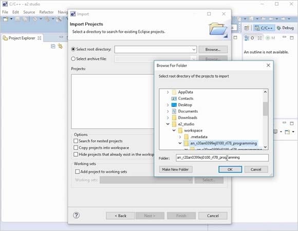
Figure 1: Specify the project to be imported.
(4) Generate square wave output code and observe output
Let’s develop the program by first using the code-generator plugin. Using the code-generator plugin, the necessary code is generated with only the parameters needing to be set. Change the width of the square wave to 100msec, which is initially configured to 100μsec in the original program and generate the code. (“Square Wave Output Setting” is shown from 02:52 of Video 2, this segment demonstrates the operation to change the pulse width.)
When the new code is generated, connect the simulator to the debugger, and observe the square wave output. The procedure of e2 studio operation is shown from "03:13" of Video 2. Here, you will connect the simulator to the debugger and the timing chart will appear (Figure 2: at “04:45” of video).
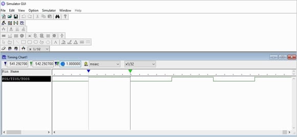
Figure 2: Timing chart displayed on the simulator (Specify the clock type as "msec." and the magnification as "1/32")
The timing chart in Figure 2 is set to observe signals that change in units of milliseconds, and realizes a function similar to logic analyzer. The cycle at which the output is turned ON/OFF can also be measured. First, interrupt (pause) the simulation and stop signal output (Fig. 3). After that, when placing the marker with the mouse on the timing chart, the time between the markers is displayed within the chart (explanation of the operation from “04:48” of Video 2).

Figure 3: Pause the program by pressing the pause button.
(5) Modify the program and change the setting
Next, modify the program so that the LED flashing can be stopped/restarted by the switch. Use the time counter here, and when it becomes 0, an interrupt will occur to turn the LED ON/OFF. Next, press switch 1 to stop the countdown of the timer, and press switch 2 to resume the countdown.
First, press the N-shaped icon in Figure 4, then disconnect the simulator and debugger. Cancel the debugger automatically to close the simulator window.

Figure 4: Disconnect the debugger by pressing N-shaped icon.
Refer to Video 2 (from “05:42”) the appearance of modifying the sample program to make the LED flashing program. When programming and debugging, it is a good idea to periodically save the changes before the build or for each work step.
(6) Connect to the debugger simulator, and observe input and output
In (4) "Generate square wave output code and observe output", the operation of RL78/G13 was only observed with a timing chart like a logic analyzer. Now there are two switch inputs in addition to the LED output. It is time to make full use of the board simulator. The appearance of the debugger that uses a board simulator operating the same as the RL78/G13 starter kit board is explained in “RL78 Board Simulator (Video 3)”.
Figure 4: Disconnect the debugger by pressing N-shaped icon.
Select “Open” from the “Simulator GUI” file menu (File>Open) and the dialogue box will appear. The dialogue box has a filter function to display only files with the specified extension. Specify “Input and output Panel File (*.pnl)” from the pull-down menu (Figure 5). By selecting “RL78G13 CG Sample e2s/G13 RSK Board2.pnl” in the dialogue box, a debugger is connected to the board level simulator (Figure 6).
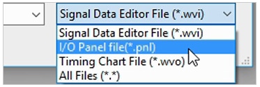
Figure 5: Filter function that displays the input and output panel
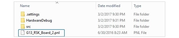
Figure 6: Select G13_RSK_Board_2.pnl
After deciding which board to be operated by the simulator, the board window will be displayed (Figure 7). As shown in the video, let’s try changing the input from switches. The flashing of the LED will change according to the program.
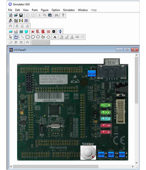
Figure 7: Displays the board intended for simulating
Confirm with the Starter Kit
Check out the starter kit operation from “RL78/G13 Renesas Starter Kit (Video 4)”. The code generated this time will completely operate the same way as on the simulator or Starter Kit. This is the advantage of development through the simulator.
How was programming without using the target hardware? Since the simulator is software driven, it does not have the same speed as the actual hardware (Starter Kit). Still, it is good enough for tracking and understanding what kind of operation the simulator is doing. Let’s take the challenge of developing an RL78-using software by making the best use of the integrated development environment “e2 studio”.
In the ”Take Advantage of Simulator Functions” series, we will explain how to use more advanced simulator functions.
By using the simulator, it is possible to confirm current consumption waveform which is difficult to check even with an actual board. Check out here for more details.
Video 4: RL78/G13 Renesas Starter Kit
Module List
- MCU Basic Structure/Operation
- Peripheral Circuitry
- Programming Language/Software Development Environment
- Peripheral Circuitry Control
- Interrupt Processing
- Possible to start without starter kit! Development method using simulators