

ECU Consolidation Trend and the Power of Virtualization
As new features like Infotainment and ADAS are added to cars, the number of ECUs installed in each vehicle is also growing. The increasing number of ECUs has some undesirable side effects: complex management of the devices, weight and power consumption are just some of these.
In order to stop this trend, the automotive industry is seeking to move from a standalone function-oriented approach to an integrated approach, where a single ECU is serving several functions.
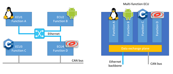
Figure 1. ECU consolidation aims to move from a single-function ECU approach (left) to Multi-function ECUs (right)
When attempting such migration to multi-function ECUs, new challenges arise: each function might need to run on a different operating system and hardware resources like CPUs, memory and peripherals must be shared among them. Furthermore, isolation and "freedom from interference" between functions need to be ensured.
Luckily, this is where virtualization technologies come to aid providing an infrastructure that allows multiple 'guest' operating systems (also called virtual machines or VMs) to execute in a safe, independent and isolated way.
Automotive Ethernet
Functions implemented in the ECUs are becoming more complex, demanding flexible interconnections and higher data transfer rates. Automotive Ethernet is emerging as a preferred choice for in-vehicle networking solutions. Ethernet has a great future potential because it provides bandwidth, lightweight cabling (e.g., unshielded single twisted pair), a huge ecosystem and solid software infrastructure. Furthermore, switched Ethernet networks offer great scalability, and Time Sensitive Network (TSN) extensions provide improved synchronization, low latency and reliability.
When a multi-function ECU uses virtualization to run several operating systems, it is a common solution to address the various VMs as if they were connected to the same physical ethernet network.
If there is only one ethernet interface, the hypervisor provides mechanisms to share the interface between VMs and usually a virtual network switch is implemented in software. As this software implementation results in overhead, hardware manufacturers are adding hardware-assisted virtualization features to their devices so that sharing can be implemented without the intervention of the hypervisor.
In this blog, we describe a proof of concept (POC) where we compare the benefit of having two VMs sharing an integrated hardware switch against a software switch.
Description of the Hardware
This POC is based on a Vehicle Computer 3 board (VC3), equipped with a Renesas R-Car H3 SoC and a TSN ethernet switch (R-Switch2). The ethernet switch is implemented on an FPGA connected to the R-Car through PCIe.
R-Switch2 has four external ports (1G-T1 connectors) and one internal port (named CPU port or tsngw) exposed to the CPU in the R-Car SoC. The interface between R-Switch2 and CPU allows an operating system running on R-Car to be the source or destination of ethernet frames.
Data between R-Switch2 and CPU is exchanged by means of multiple queues. Each queue is represented by a list of descriptors, that reside in main memory and are set up by the software running on the CPU:
- The descriptors in an RX queue tell the R-Switch2 hardware where incoming Ethernet frames for the CPU should be copied in the main memory
- The descriptors in a TX queue tell the R-Switch2 hardware where the CPU has placed the frames it wishes to send out so that the hardware knows where in main memory the data should be fetched from
In the case of a hypervisor running on the CPU, queues can be assigned to specific guest OSes for independent data handling.
Description of the Software
For this proof of concept, Xen v4.14 was chosen as the hypervisor. Additional frontend and backend drivers were developed to share the R-Switch2 hardware as an alternative to a typical Xen Bridged Network (more info here). Two guest operating systems are running on Xen (also called domains):
- dom0: a privileged domain that has direct access to most of the R-Car peripherals and the R-Switch
- domU: an unprivileged domain that doesn't have direct access to any specific hardware device. However, domU has access to two R-Switch2 queues (one RX and one TX)
Figure 2 below shows this configuration.
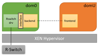
Figure 2. Software configuration for this POC
The communication between the frontend and backend drivers is used only in the following cases:
- At initialization time, the frontend sends a request to reserve two R-Switch2 queues (1 TX and 1 RX)
- At run-time, the frontend uses this communication channel to notify the R-Switch2 hardware through the backend that the TX queue is ready to be processed. It is also used by the backend to notify the frontend every time new data is available in domU’s RX queue
Note that after the initial handshake needed to set up the queues for domU, the frontend driver is able to transmit and receive frames just by directly accessing the same queues processed by the R-Switch2 hardware, with minimal intervention from dom0 side. This is an advantage compared to other SW networking solutions for virtual machines, where usually the frames for domU are shared with the backend driver and re-routed by the network stack in dom0.
For example, when domU wants to transmit some frames over the network, the steps involved in using the shared R-Switch2 solution are the following (depicted in Figure 3):
- domU writes the data to its own TX queue
- domU notifies the R-Switch2 HW (through the backend) that the queue is ready to be processed
- The R-Switch2 HW fetches the data directly from domU queue
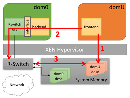
Figure 3. Example of packet transmission from domU (R-Switch2 sharing)
On the other side, when using a Xen Bridged Network the steps involved when transmitting frames from domU are (see Figure 4):
- domU writes the data to be transmitted into memory
- The memory is shared with the backend in dom0
- The backend forwards the packets to the Xen Bridge
- Packets are routed through dom0 network stack and eventually to the network interface driver
- The driver copies the packets’ data into the NIC queues
- The NIC accesses the data from memory
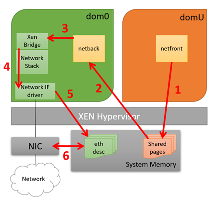
Figure 4. Example of packet transmission from domU (Xen Bridged Network)
Performance and Comparison
The performance of the system was measured by generating a constant bitrate UDP stream from/to domU and measuring the CPU load on both dom0 and domU at the same time.
The reason why we measure the CPU usage of dom0 even though the network frames are transmitted/received from domU is that we expect to see higher loads in the case where a virtual switch is implemented in software because domU packets need to be re-routed by dom0’s network stack.
The solution implemented in this POC was then compared with a Xen Bridged Network, which is a common SW solution that implements a virtual switch and allows multiple virtual machines to be connected on the same network.
The results are depicted in Figure 5 and Figure 6 and confirm our assumption. When using the R-Switch2 sharing solution, dom0 CPU load is about 50% lower compared to the Xen Bridged network, while domU CPU load is almost the same.

Figure 5. CPU load during domU Receive Test (constant data rate of 1 Gbps)
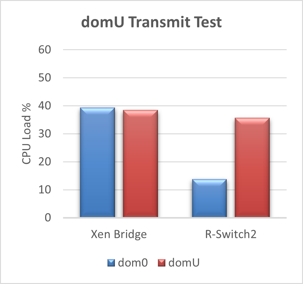
Figure 6. CPU load during domU Transmit Test (constant data rate of 600 Mbps)
The residual dom0 CPU load in the R-Switch2 case is caused by event notification from/to domU, i.e. dom0 notifies domU when new incoming data is available, or dom0 forwards to the R-Switch2 HW the request from domU to start processing the TX queue.
In the case of a software-based switch like Xen Bridge, dom0 has the additional task to route domU packets and this might become a bottleneck in the system. In our solution, the routing of domU packets is done in hardware by the integrated network switch, freeing up CPU resources and improving the isolation between the two domains.
Conclusion
An integrated hardware switch can make a software switch simplified or even redundant to free up resources for application processing rather than housekeeping tasks. The evaluation has shown that more than 50% of valuable CPU resource was saved when using hardware-assisted virtualization. Renesas R-Switch2 support of multiple receive and transmit queues proved to be a clear advantage in the context of ECU consolidation via virtualization. This feature together with HW support for L2 and L3 routing and TSN extensions makes it the perfect choice for implementing the ECU of tomorrow.
Links:
Learn more about Vehicle Computer 3
Learn more about R-Car H3
Read other blog posts in this series: The Art of Networking Part 1, Part 2