

Hello, my name is Takeo Mimura. My current responsibility is the RA6T1 Group MCUs, the latest members of the RA MCU Family that are designed to make motor control easy.
Motor control for home appliances is growing fast, and if you’re like me, you have probably bought a new cleaning robot recently. In the future, I believe that motor control equipment will become more familiar and make our lives easier.
If you’re an engineer challenged with a motor control application design for the first time, I will introduce a solution that can make motor control easy.
This blog will show you in three simple steps how to use the RA6T1 Motor Control Evaluation System, which consists of the RA6T1 Renesas Solution Starter Kit (RSSK) and the Renesas Motor Workbench.
Step 1: Hardware Setup
Step 2: Software Downloads
Step 3: Renesas Motor Workbench Installation
Before highlighting these steps, I will briefly introduce the RA6T1 motor RSSK and Renesas Motor Workbench.
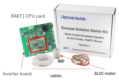
The RA6T1 motor RSSK is designed for motor control immediately after opening the box. It includes the RA6T1 MCU (Arm® Cortex®-M4 core at 120MHz with 512KB Flash) CPU card, inverter board, and BLDC motor and cables. The power supply is not included. You will need to connect to your own power supply, separately.
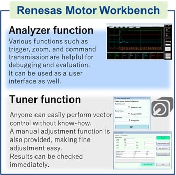
Renesas Motor Workbench can display waveforms, like an oscilloscope, as well as motor control variables while driving the motor.
By using the Analyzer and Tuner functions, it is possible to improve the efficiency of your motor control equipment during development. Sample software, application notes (sensorless vector control), schematics, and more can be obtained from the RA6T1 motor RSSK product page.
Now, let's take a look at the three steps. It's really easy to set up the RA6T1 motor RSSK.
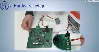
Step 1: Set Up Your Hardware
- Check the jumper pin settings on the RA6T1 CPU card.
- Connect the motor and various cables.
- Connect the stabilized power supply, the motor moves.
After powering on, the rotation direction can be changed by moving the volume resistance of the inverter board.
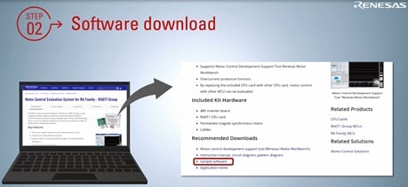
Step 2: Software Downloads
- The RA6T1 CPU card is equipped with an on-board debugger.
- When writing a sample program, it is possible to write by connecting the RA6T1 CPU card and PC using s USB cable connection.
- The sample program is available on the RA6T1 motor RSSK product page.
Sample programs are available in a buildable state. After launching the project, you can immediately write the sample program to RA6T1.
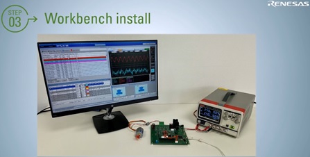
Step 3: Renesas Motor Workbench Installation
- The Renesas Motor Workbench is available for download from the RA6T1 motor RSSK product page.
- The downloaded file contains an installer, which you can install.
- The hardware setup is completed by connecting the RA6T1 CPU card and the inverter board with a cable and connecting the inverter board and PC with a USB cable.
The hardware setup is done. I hope this has helped remove the hurdles to getting started, allowing you to start your motor control design using Renesas’ RA6T1 Motor control solution.
For information to help you with your motor control design using an RA6T1 MCU, please refer to the following links.
Motor Control Evaluation System for the RA Family - RA6T1 Group
RA6T1 32-bit MCU product page
RA6T1 Motor Control Evaluation System Introduction video
RA6T1 Motor Control Evaluation System Setup video